2. Poisson 方程 II Poisson Equation II#
内容提要
围绕 Poisson 方程的进阶专题: 等参有限元方法、间断有限元方法 (SIPG)、自由度的分布、par_loop 与 op2.par_loop、指示函数、Dirac delta 源项、网格自适应、变分求解器的回调函数, 以及高振荡函数的插值误差. 请先阅读 Poisson 方程 I.
Overview
Further topics around the Poisson equation: isoparametric finite element methods, discontinuous Galerkin methods (SIPG), the layout of degrees of freedom, par_loop and op2.par_loop, indicator functions, Dirac-delta source terms, adaptive mesh refinement, variational solver callbacks, and the interpolation error of highly oscillatory functions. Read the chapter Poisson Equation I first.
2.1. 等参有限元方法 Isoparametric finite element methods#
在曲边区域上使用直边网格时, 边界只能被逐段线性地逼近, 几何误差为 \(O(h^2)\). 这对线性元没有影响, 但对 \(p \ge 2\) 的高次元, 边界逼近误差会盖过单元的逼近能力, 使收敛阶失去最优性 (本节的数值实验中, 不作处理时 \(H^1\) 收敛阶停在 \(1.5\) 附近). 等参有限元方法用与有限元同次的多项式映射逼近曲边界, 从而恢复最优收敛阶.
On a domain with curved boundary, a straight-edged mesh approximates the boundary only piecewise linearly, with a geometric error of \(O(h^2)\). This does not affect linear elements, but for elements of degree \(p \ge 2\) the boundary approximation error dominates the approximation power of the elements and the convergence rates lose optimality (in the numerical experiment of this section, the \(H^1\) rate stalls around \(1.5\) without treatment). Isoparametric finite element methods approximate the curved boundary by a polynomial mapping of the same degree as the elements, restoring the optimal rates.
Firedrake 中网格坐标存放在一个函数 (Function) 里: 修改该函数的值就可以移动网格; 把坐标函数换成高次空间中的函数, 就得到等参元对应的映射. 下面先熟悉坐标的存取和移动网格, 再给出等参元的构造.
In Firedrake the mesh coordinates are stored in a Function: modifying its values moves the mesh, and replacing it by a function in a higher-degree space yields the mapping of isoparametric elements. We first get familiar with accessing coordinates and moving the mesh, and then construct the isoparametric mapping.
2.1.1. 网格坐标的存取和移动 Accessing and moving mesh coordinates#
坐标以 numpy 数组的形式存储, 有四种访问方式:
The coordinates are stored as numpy arrays, accessible in four ways:
mesh = RectangleMesh(10, 10, 1, 1)
mesh.coordinates.dat.data
mesh.coordinates.dat.data_ro
mesh.coordinates.dat.data_with_halos
mesh.coordinates.dat.data_ro_with_halos
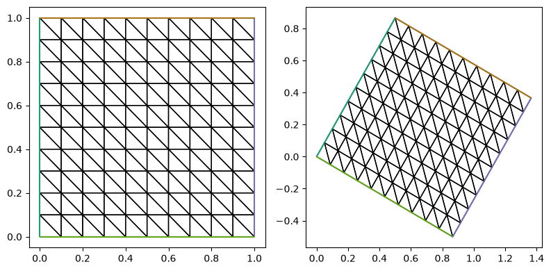
后缀 _ro 表示只读视图, _with_halos 表示包含进程间的 halo 区域; 单进程运行时 data 和 data_with_halos 相同, 关于 halo 请参考 PyOP2 的 MPI 文档. 下面把网格整体旋转 \(\pi/6\):
The suffix _ro denotes a read-only view and _with_halos includes the halo regions shared between processes; in serial runs data and data_with_halos coincide — see the PyOP2 MPI documentation for halos. The following rotates the whole mesh by \(\pi/6\):
from firedrake import RectangleMesh
from py.intro_utils import triplot
import numpy as np

import matplotlib.pyplot as plt

test_mesh = RectangleMesh(10, 10, 1, 1)

fig, ax = plt.subplots(1, 2, figsize=[8, 4])
handle = triplot(test_mesh, axes=ax[0])

theta = np.pi/6
R = np.array([[np.cos(theta), - np.sin(theta)],
              [np.sin(theta),   np.cos(theta)]])

test_mesh.coordinates.dat.data_with_halos[:] = test_mesh.coordinates.dat.data_ro_with_halos[:]@R

handle = triplot(test_mesh, axes=ax[1])
fig.tight_layout()
2.1.2. 等参元的构造 Constructing the isoparametric mapping#
等参元映射通过更改坐标向量场实现: 从线性网格出发, 把坐标插值到高次空间, 再把落在边界上的自由度移动到曲边界上. 以单位圆为例, 下面给出两种做法.
The isoparametric mapping is realized by changing the coordinate field: starting from a linear mesh, interpolate the coordinates into a higher-degree space and move the boundary degrees of freedom onto the curved boundary. For the unit disk, two constructions are given below.
2.1.2.1. 简单映射边界点 Moving only the boundary points#
最简单的做法是只把落在边界上的自由度拉到曲边界上:
The simplest construction only snaps the degrees of freedom lying on the boundary onto the curved boundary:
def points2bdy(points):
    r = np.linalg.norm(points, axis=1).reshape([-1, 1])
    return points/r

def make_high_order_mesh_map_bdy(m, p):
    coords = m.coordinates
    V_p = VectorFunctionSpace(m, 'CG', p)
    coords_p = Function(V_p, name=f'coords_p{p}').interpolate(coords)

    bc = DirichletBC(V_p, 0, 'on_boundary')
    points = coords_p.dat.data_ro_with_halos[bc.nodes]
    coords_p.dat.data_with_halos[bc.nodes] = points2bdy(points)

    return Mesh(coords_p)
2.1.2.2. 同时移动边界单元的内点 Moving interior points of boundary cells as well#
上面的映射只移动了落在边界上的自由度. 更好的做法是从 2 次开始逐次升阶, 每一阶都把边界自由度贴到曲边界上, 这样边界单元的内部自由度也随之移动:
The previous mapping only moves the degrees of freedom lying on the boundary. A better construction raises the degree one step at a time, snapping the boundary degrees of freedom onto the curved boundary at each step, so that the interior degrees of freedom of boundary cells move along:
def make_high_order_mesh_simple(m, p):
    if p == 1:
        return m

    coords_1 = m.coordinates
    coords_i = coords_1
    for i in range(2, p+1):
        coords_im1 = coords_i
        V_i = VectorFunctionSpace(m, 'CG', i)
        bc = DirichletBC(V_i, 0, 'on_boundary')
        coords_i = Function(V_i, name=f'coords_p{i}').interpolate(coords_im1)
        coords_i.dat.data_with_halos[bc.nodes] = \
            points2bdy(coords_i.dat.data_ro_with_halos[bc.nodes])

    return Mesh(coords_i)
这是一个简单的实现, 并不完全符合文献 [Len86] 中等参元映射的构造方式. 一个完整的实现见 py/make_mesh_circle_in_rect.py 中的函数 make_high_order_coords_for_circle_in_rect, 它实现了内部具有圆形界面的矩形区域上的等参映射.
This is a simplified construction that does not fully follow the isoparametric mapping of [Len86]. For a complete implementation see the function make_high_order_coords_for_circle_in_rect in py/make_mesh_circle_in_rect.py, which builds the isoparametric mapping on a rectangle with an interior circular interface.
2.1.3. 数值实验 Numerical experiment#
在单位圆盘 \(\Omega = \{ x^2 + y^2 < 1 \}\) 上求解 Poisson 方程
取真解 \(u = 1 - (x^2 + y^2)^{3.5}\) (它在单位圆边界上恰好为零), 源项 \(f\) 由真解代入方程得到. 配套脚本 py/possion_convergence_circle.py 在一列逐级加密的圆盘网格上求解, 输出相对 \(H^1\)、\(L^2\) 误差及收敛阶, 并比较三种情形: 不用等参元、等参元只移动边界点、等参元同时移动边界单元的内点. 在 jupyter-lab 中运行:
On the unit disk \(\Omega = \{ x^2 + y^2 < 1 \}\) we solve the Poisson equation
with the exact solution \(u = 1 - (x^2 + y^2)^{3.5}\) (which vanishes exactly on the unit circle); the source \(f\) is obtained by substituting the exact solution into the equation. The companion script py/possion_convergence_circle.py solves on a sequence of refined disk meshes, prints the relative \(H^1\) and \(L^2\) errors with their convergence rates, and compares three cases: no isoparametric elements, isoparametric elements moving only the boundary points, and isoparametric elements moving the interior points of boundary cells as well. In jupyter-lab run:
%run python py/possion_convergence_circle.py -max_degree 3 -exact "1 - (x[0]**2 + x[1]**2)**3.5"
或在命令行运行 or from the command line
python py/possion_convergence_circle.py -max_degree 3 -exact "1 - (x[0]**2 + x[1]**2)**3.5"
输出如下: The output reads:
$ python py/possion_convergence_circle.py -max_degree 3 -exact "1 - (x[0]**2 + x[1]**2)**3.5"
Exact solution:  1 - (x[0]**2 + x[1]**2)**3.5

p = 1; Use isoparametric: False; Only move boundary: False.
    Rel. H1 errors: 2.15e-01 1.10e-01 5.51e-02
            orders:       --     1.00     1.00
    Rel. L2 errors: 2.97e-02 7.65e-03 1.93e-03
            orders:       --     2.01     2.01

p = 2; Use isoparametric: False; Only move boundary: False.
    Rel. H1 errors: 2.57e-02 8.23e-03 2.75e-03
            orders:       --     1.69     1.60
    Rel. L2 errors: 8.05e-03 1.98e-03 4.90e-04
            orders:       --     2.08     2.04

p = 2; Use isoparametric: True; Only move boundary: False.
    Rel. H1 errors: 2.05e-02 5.16e-03 1.28e-03
            orders:       --     2.04     2.03
    Rel. L2 errors: 1.32e-03 1.66e-04 2.06e-05
            orders:       --     3.08     3.05

p = 3; Use isoparametric: False; Only move boundary: False.
    Rel. H1 errors: 1.47e-02 5.18e-03 1.83e-03
            orders:       --     1.54     1.52
    Rel. L2 errors: 7.86e-03 1.96e-03 4.87e-04
            orders:       --     2.06     2.03

p = 3; Use isoparametric: True; Only move boundary: True.
    Rel. H1 errors: 2.88e-03 5.12e-04 9.07e-05
            orders:       --     2.56     2.53
    Rel. L2 errors: 1.07e-04 9.18e-06 7.98e-07
            orders:       --     3.63     3.57

p = 3; Use isoparametric: True; Only move boundary: False.
    Rel. H1 errors: 1.03e-03 1.25e-04 1.53e-05
            orders:       --     3.12     3.07
    Rel. L2 errors: 4.47e-05 2.70e-06 1.64e-07
            orders:       --     4.16     4.09
输出验证了等参元的作用: \(p = 1\) 时线性网格即可达到最优阶; \(p \ge 2\) 时若仍用线性网格, 边界逼近误差主导, \(H^1\) 阶停在 \(1.5\) 左右, \(L^2\) 阶约为 \(2\); 使用等参元后恢复最优阶 (\(H^1\) 阶 \(p\), \(L^2\) 阶 \(p+1\)). 只把边界点移动到边界上的简化映射 (Only move boundary: True) 得到的阶数介于两者之间.
The output shows the effect of isoparametric elements: for \(p = 1\) the linear mesh already attains the optimal rates; for \(p \ge 2\) on a linear mesh the boundary approximation error dominates and the \(H^1\) rate stalls around \(1.5\) with an \(L^2\) rate of about \(2\); with isoparametric elements the optimal rates (\(p\) in \(H^1\) and \(p+1\) in \(L^2\)) are recovered. The simplified mapping that only moves the boundary points (Only move boundary: True) gives rates in between.
2.2. 间断有限元方法 Discontinuous Galerkin methods#
2.2.1. UFL 符号和测度 UFL symbols and measures#
间断有限元的变分形式含有内部边上的积分, 需要用到函数在边两侧的限制及其组合:
u('+'),u('-'): 函数在内部边正侧和负侧的值;avg(u): 平均值, 即(u('+') + u('-'))/2;jump(u, n) = u('+')*n('+') + u('-')*n('-')与jump(u) = u('+') - u('-'): 跳量;FacetNormal(mesh): 单位外法向;CellDiameter(mesh): 网格尺寸 (见 Poisson 方程 I 的网格尺寸一节);ds: 外部边上的积分;dS: 内部边上的积分. 注意区分大小写.
The variational forms of discontinuous Galerkin methods contain integrals over interior facets, which involve the restrictions of functions to the two sides of a facet and their combinations:
u('+'),u('-'): the values of a function on the plus and minus sides of an interior facet;avg(u): the average(u('+') + u('-'))/2;jump(u, n) = u('+')*n('+') + u('-')*n('-')andjump(u) = u('+') - u('-'): jumps;FacetNormal(mesh): the unit outward normal;CellDiameter(mesh): the mesh size (see the mesh-size section of chapter Poisson I);ds: integration over exterior facets;dS: integration over interior facets. Mind the capitalization.
2.2.2. 变分形式 Variational form#
对 Poisson 方程使用对称内罚方法 (SIPG) [Arn82], Dirichlet 边界条件以弱形式施加 (各类 DG 方法的统一分析见 [ABCM02]). 变分形式为: 求 \(u\) 使得对任意 \(v\)
For the Poisson equation we use the symmetric interior penalty method (SIPG) [Arn82], with the Dirichlet boundary condition imposed weakly (see [ABCM02] for a unified analysis of DG methods). The variational form reads: find \(u\) such that for all \(v\)
其中 \(F_i\), \(F_o\) 分别为内部边和外部边的集合; 在内部边 \(F_i\) 上,
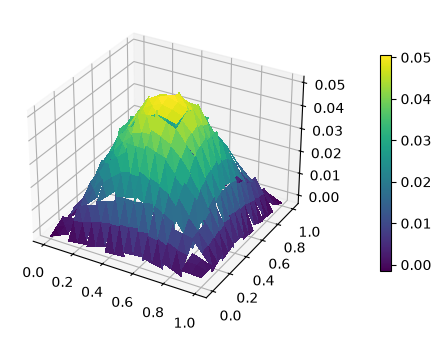
在外部边 \(F_o\) 上, 跳量 \([vn] := v\,n\), 均值 \(\{u\} := u\) (此时 \([un]\cdot[vn] = uv\)); \(\alpha\) 为罚参数, 需要足够大以保证稳定性, 其取法可参考 [ERiviere07], [Sha05]. 下面在 DG1 空间中求解:
where \(F_i\) and \(F_o\) denote the sets of interior and exterior facets; on the interior facets \(F_i\),
while on the exterior facets \(F_o\) the jump and average reduce to \([vn] := v\,n\) and \(\{u\} := u\) (so that \([un]\cdot[vn] = uv\)); \(\alpha\) is the penalty parameter, which must be large enough for stability — see [ERiviere07], [Sha05] for its choice. We solve in the DG1 space:
from firedrake import *
import matplotlib.pyplot as plt

mesh = RectangleMesh(8, 8, 1, 1)

DG1 = FunctionSpace(mesh, 'DG', 1)
u, v = TrialFunction(DG1), TestFunction(DG1)

x, y = SpatialCoordinate(mesh)
f = sin(pi*x)*sin(pi*y)

h = Constant(2.0)*Circumradius(mesh)
alpha = Constant(1)

n = FacetNormal(mesh)

a = inner(grad(u), grad(v))*dx \
  - dot(avg(grad(u)), jump(v, n))*dS \
  - dot(jump(u, n), avg(grad(v)))*dS \
  + alpha/avg(h)*dot(jump(u, n), jump(v, n))*dS \
  - dot(grad(u), v*n)*ds \
  - dot(u*n, grad(v))*ds \
  + alpha/h*u*v*ds

L = f*v*dx

u_h = Function(DG1, name='u_h')
solve(a == L, u_h)
fig, ax = plt.subplots(figsize=[8, 4], subplot_kw=dict(projection='3d'))
ts = trisurf(u_h, axes=ax)
cbar = fig.colorbar(ts, ax=ax, shrink=0.7, pad=0.1)
2.2.3. 收敛阶测试 Convergence test#
沿用简单完整示例的算例 (真解 \(u = \sin(\pi x)\sin(\pi y)/(2\pi^2)\)), 在一列加密网格上验证 SIPG 的收敛阶. 与上面的演示不同, 这里边界条件完全用弱形式施加 (不再传入 DirichletBC); 另外罚参数需要随次数增大 (与 \(p^2\) 成比例 [SchotzauST03]), 这里取 \(\alpha = 4p^2\). \(L^2\) 误差应按最优阶 \(O(h^{p+1})\) 收敛:
Using the problem of the first complete example (exact solution \(u = \sin(\pi x)\sin(\pi y)/(2\pi^2)\)), we verify the convergence rates of SIPG on a sequence of refined meshes. Unlike the demonstration above, the boundary condition is imposed weakly only (no DirichletBC is passed); moreover the penalty parameter must grow with the degree (proportional to \(p^2\) [SchotzauST03]), here \(\alpha = 4p^2\). The \(L^2\) error should converge at the optimal rate \(O(h^{p+1})\):
import numpy as np

def solve_sipg(N, p):
    mesh = RectangleMesh(N, N, 1, 1)
    V = FunctionSpace(mesh, 'DG', p)
    u, v = TrialFunction(V), TestFunction(V)
    x, y = SpatialCoordinate(mesh)
    f = sin(pi*x)*sin(pi*y)

    h = Constant(2.0)*Circumradius(mesh)
    alpha = Constant(4*p**2)
    n = FacetNormal(mesh)

    a = inner(grad(u), grad(v))*dx \
      - dot(avg(grad(u)), jump(v, n))*dS \
      - dot(jump(u, n), avg(grad(v)))*dS \
      + alpha/avg(h)*dot(jump(u, n), jump(v, n))*dS \
      - dot(grad(u), v*n)*ds \
      - dot(u*n, grad(v))*ds \
      + alpha/h*u*v*ds
    L = f*v*dx

    u_h = Function(V)
    solve(a == L, u_h)
    u_exact = sin(pi*x)*sin(pi*y)/(2*pi**2)
    return errornorm(u_exact, u_h)

for p in (1, 2):
    Ns = [8, 16, 32, 64]
    errors = np.array([solve_sipg(N, p) for N in Ns])
    orders = np.log(errors[:-1]/errors[1:])/np.log(2)
    print(f'p = {p}:')
    print('    L2 errors:', ' '.join(f'{e:.2e}' for e in errors))
    print('       orders:', ' '.join(['      --'] + [f'{o:8.2f}' for o in orders]))
p = 1:
    L2 errors: 5.16e-04 1.29e-04 3.25e-05 8.15e-06
       orders:       --     2.00     1.99     1.99
p = 2:
    L2 errors: 1.67e-05 2.09e-06 2.62e-07 3.28e-08
       orders:       --     3.00     3.00     3.00
tsfc:WARNING Estimated quadrature degree 12 more than tenfold greater than any argument/coefficient degree (max 1)
2.2.4. 内部边界的正负侧 Plus and minus sides of interior facets#
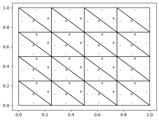
内部边的正负侧由网格的内部编号决定, 一般无法预先指定. 下面的代码用 DG0 (单元) 和 HDivT (边) 空间的指示函数, 通过 assemble(u('+')*u_e('+')*dS) 是否非零来判断每条内部边相对相邻单元的侧别, 并把 +/- 标注在图中对应位置, 图片保存为 pdf 文件.
Which side of an interior facet is plus or minus is determined by internal mesh numbering and cannot be prescribed in general. The code below uses indicator functions in the DG0 (cell) and HDivT (facet) spaces, decides the side of each interior facet relative to its neighboring cells by testing whether assemble(u('+')*u_e('+')*dS) is nonzero, annotates +/- at the corresponding positions, and saves the figure as a pdf file.
from firedrake import *
from firedrake.petsc import PETSc

import os, sys
import numpy as np
import matplotlib.pyplot as plt
# plt.rcParams.update({'font.size': 14})

N = PETSc.Options().getInt('N', default=4)

m = RectangleMesh(N, N, 1, 1)
V = FunctionSpace(m, 'DG', 0)
Vc = VectorFunctionSpace(m, 'DG', 0)
V_e = FunctionSpace(m, 'HDivT', 0)
V_ec = VectorFunctionSpace(m, 'HDivT', 0)

x, y = SpatialCoordinate(m)
u = Function(V, name='u')
uc = Function(Vc).interpolate(m.coordinates)
u_e = Function(V_e, name='u_e')
u_ec = Function(V_ec).interpolate(m.coordinates)

ncell = len(u.dat.data_ro)

factor = 0.7
for i in range(ncell):
    cell = V.cell_node_list[i][0]
    u.dat.data_with_halos[:] = 0
    u.dat.data_with_halos[cell] = 1
    es = V_e.cell_node_list[i]
    cc = uc.dat.data_ro_with_halos[cell, :]

    vertex = m.coordinates.dat.data_ro_with_halos[
        m.coordinates.function_space().cell_node_list[i]
    ]
    vertex = np.vstack([vertex, vertex[0]])
    plt.plot(vertex[:, 0], vertex[:, 1], 'k', lw=1)

    for e in es:
        u_e.dat.data_with_halos[:] = 0
        u_e.dat.data_with_halos[e] = 1
        ec = u_ec.dat.data_ro_with_halos[e, :]
        dis = ec - cc

        v_p, v_m = assemble(u('+')*u_e('+')*dS), assemble(u('-')*u_e('-')*dS)
        _x = cc[0] + factor*dis[0]
        _y = cc[1] + factor*dis[1]

        plt.text(_x, _y, '+' if v_p > 0 else '-', ha='center', va='center')

rank, size = m.comm.rank, m.comm.size
if not os.path.exists('figures'):
    os.makedirs('figures')
plt.savefig(f'figures/dgflag_{size}-{rank}.pdf')
2.3. 自由度的分布 Layout of degrees of freedom#
本节介绍自由度在网格上的分布: 每个单元关联哪些自由度, 以及自由度在参考单元上的位置. 这是编写自定义内核 (如下一节的 par_loop) 和理解矩阵组装的基础.
This section describes how degrees of freedom are laid out on the mesh: which degrees of freedom each cell carries, and where they sit on the reference cell. This is the basis for writing custom kernels (such as the par_loops of the next section) and for understanding matrix assembly.
2.3.1. 单元上的自由度编号 The cell node map#
设 V 是网格上的有限元函数空间 (下面的代码取 8×8 矩形网格上的 P1 空间), 单元与自由度的对应关系 (cell node map) 可以从 V 上取得:
V.dim(): 自由度总数;V.cell_node_list: 每个单元的自由度全局编号数组 (与V.cell_node_map().values相同).
下面打印前两个单元的自由度全局编号:
Let V be a finite element function space on a mesh (the code below uses the P1 space on an 8×8 rectangle mesh). The correspondence between cells and degrees of freedom (the cell node map) is available from V:
V.dim(): the total number of degrees of freedom;V.cell_node_list: the array of global dof numbers of each cell (same asV.cell_node_map().values).
Print the global dof numbers of the first two cells:
mesh = RectangleMesh(8, 8, 1, 1)
V = FunctionSpace(mesh, 'CG', 1)

# the global numers of the dofs in the first 2 elements
for i in range(2):
    print(f"cell {i}: ", V.cell_node_list[i])
cell 0:  [0 1 2]
cell 1:  [0 1 3]
示例: 第一个三角形的坐标 Example: coordinates of the first triangle
coords = mesh.coordinates
V_c = coords.function_space()
dof_numbers = V_c.cell_node_list[0]

for i in dof_numbers:
    print(f"vertex {i}:", coords.dat.data_ro_with_halos[i])
vertex 0: [0.125 0.   ]
vertex 1: [0.    0.125]
vertex 2: [0. 0.]
2.3.2. 参考单元上的自由度 Degrees of freedom on the reference cell#
V.finat_element 给出参考单元上的有限元定义, entity_dofs() 返回每类几何实体 (顶点、边、面、体) 上的自由度编号:
V.finat_element describes the finite element on the reference cell; entity_dofs() returns the dof numbers attached to each geometric entity (vertex, edge, face, volume):
V = FunctionSpace(mesh, 'CG', 2)
element = V.finat_element

print("cell: ",  element.cell)
print("degree: ", element.degree)
cell:  UFCTriangle(2, ((0.0, 0.0), (1.0, 0.0), (0.0, 1.0)), {0: {0: (0,), 1: (1,), 2: (2,)}, 1: {0: (1, 2), 1: (0, 2), 2: (0, 1)}, 2: {0: (0, 1, 2)}})
degree:  2
element.entity_dofs() # dofs for every entity (vertex, edge, face, volume)
{0: {0: [0], 1: [3], 2: [5]}, 1: {2: [1], 1: [2], 0: [4]}, 2: {0: []}}
参考单元中几何实体 (entity) 的连接关系见代码:
详细的介绍可以参考 [ALM12].
The connectivity of the geometric entities of the reference cells is defined in the code:
See [ALM12] for a detailed introduction.
2.3.3. FiniteElement 的 variant 参数示例 The variant argument of FiniteElement#
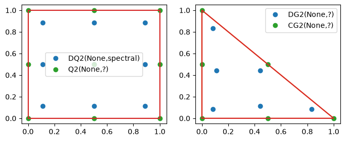
FiniteElement 的 variant 参数控制自由度节点在参考单元上的摆放方式 (如 spectral, equispaced). 下面分别在四边形和三角形单元上画出 DQ/DG 与 CG 空间的节点位置: 四边形上 DQ 的默认 variant 为 spectral, 节点并不等距.
The variant argument of FiniteElement controls how the nodes are placed on the reference cell (e.g. spectral, equispaced). Below, the node positions of the DQ/DG and CG spaces are plotted on a quadrilateral and on a triangle: on quadrilaterals the default variant of DQ is spectral, whose nodes are not equally spaced.
from firedrake import *
import ufl
import numpy as np
import matplotlib.pyplot as plt
from scipy.spatial import ConvexHull


def show_dofs(V, ax=None):
    """Show the position of the nodes in the dual space"""
    if ax is None:
        fig, ax = plt.subplots(figsize=[4, 3])
    ele = V.ufl_element()
    ps = V.finat_element.dual_basis[1]
    ax.plot(ps.points[:, 0], ps.points[:, 1], 'o', label=ele.shortstr())
    cell = V.finat_element.cell
    vertices = np.array(cell.get_vertices())
    hull = ConvexHull(vertices)
    index = list(hull.vertices)
    index.append(index[0])
    ax.plot(vertices[index, 0], vertices[index, 1])
    ax.legend() # (bbox_to_anchor=(1, 1))
    return ax


p = 2 # or set to 3 to make it clear
# https://www.firedrakeproject.org/variational-problems.html#id14
# fe = FiniteElement("DQ", mesh.ufl_cell(), p, variant="equispaced")
mesh = RectangleMesh(1, 1, 1, 1, quadrilateral=True)
fe = FiniteElement("DQ", mesh.ufl_cell(), p, variant="spectral")  # default
V1 = FunctionSpace(mesh, fe)
V2 = FunctionSpace(mesh, 'CG', p)

fig, ax = plt.subplots(1, 2, figsize=[8, 3])
show_dofs(V1, ax=ax[0])
show_dofs(V2, ax=ax[0])

mesh = RectangleMesh(1, 1, 1, 1, quadrilateral=False)
V1 = FunctionSpace(mesh, 'DG', p)
V2 = FunctionSpace(mesh, 'CG', p)
show_dofs(V1, ax=ax[1])
show_dofs(V2, ax=ax[1])
<Axes: >
2.4. par_loop 与 op2.par_loop par_loop and op2.par_loop#
Firedrake 提供两层相关接口, 用于在网格实体上执行用户给定的内核. 高层 par_loop 面向 Function 和 UFL 测度, 会自动取得函数空间的自由度映射; 底层 op2.par_loop 直接面向 PyOP2 的迭代集合、Dat 和映射, 写法更显式. 两者都适合实现框架没有直接提供的逐实体计算. 本节先用两个四面体面上的算例介绍高层接口, 再说明如何直接调用底层接口.
Firedrake provides two related interfaces for executing user-supplied kernels over mesh entities. The high-level par_loop works with Function objects and UFL measures and obtains function-space dof maps automatically; the lower-level op2.par_loop works directly with PyOP2 iteration sets, Dat objects, and maps, making these details explicit. Both are useful for entity-wise operations not directly provided by the framework. We first introduce the high-level interface with two examples on tetrahedron facets, then show how to call the lower-level interface directly.
2.4.1. 高层 par_loop 接口 The high-level par_loop interface#
高层 par_loop 的第一个参数是用 Loopy 语法描述的内核 (迭代域和指令), 第二个参数是决定迭代范围的 UFL 测度, 第三个参数是将内核变量名映射到 Function 及其读写方式的字典. 先查看内置帮助:
The first argument of the high-level par_loop is a kernel described in Loopy syntax (an iteration domain and instructions); the second is a UFL measure selecting the iteration region; the third is a dictionary mapping kernel variable names to Function objects and their access modes. First inspect the built-in help:
help(par_loop)
par_loop 示例中的局部编号 Local numbering in the par_loop examples
下面两个算例都要从四面体顶点的坐标计算面上的量, 因此先说明参考单元上的局部编号. 参考四面体的顶点编号为 \(0,1,2,3\), 局部面 \(i\) 是不含顶点 \(i\) 的对面: 面 0 由顶点 \((1,2,3)\) 组成, 面 1 由 \((0,2,3)\) 组成, 依此类推. HDivT 0 次元在每个面上恰有一个自由度, 其局部自由度编号与局部面编号一致.
这里的编号都是参考单元内的局部编号. 不同单元共享面的全局编号以及面方向可能不同, 但 par_loop 会通过函数空间的映射把局部自由度对应到正确的全局自由度. 下面直接查看 FInAT 给出的参考单元拓扑和 HDivT 自由度分布:
Both examples below compute facet quantities from tetrahedron vertex coordinates, so we first describe the local numbering on the reference cell. The vertices of the reference tetrahedron are numbered \(0,1,2,3\), and local facet \(i\) is opposite vertex \(i\): facet 0 contains vertices \((1,2,3)\), facet 1 contains \((0,2,3)\), and so on. The lowest-order HDivT space has one degree of freedom per facet, and its local dof numbers agree with the local facet numbers.
All these numbers are local to the reference cell. The global number and orientation of a facet shared by different cells may differ, but par_loop uses the function-space maps to associate local degrees of freedom with the correct global ones. We can inspect the reference-cell topology and the HDivT dof layout reported by FInAT:
mesh = UnitCubeMesh(1, 1, 1)
V_facet = FunctionSpace(mesh, 'HDivT', 0)

print('facet vertices:', V_facet.finat_element.cell.get_topology()[2])
print('facet dofs:', V_facet.finat_element.entity_dofs()[2])
facet vertices: {0: (1, 2, 3), 1: (0, 2, 3), 2: (0, 1, 3), 3: (0, 1, 2)}
facet dofs: {0: [0], 1: [1], 2: [2], 3: [3]}
例 1: 计算四面体面的外接圆半径 Example 1: circumradius of tetrahedron faces
下面的 args 字典把内核变量 A 映射到存放结果的 HDivT 函数, 把 B 映射到网格坐标函数. 因而在内核中, A[i] 表示局部面 \(i\) 上的输出自由度, B[j, :] 表示局部顶点 \(j\) 的三维坐标. 对固定的 i, (i+1)%4、(i+2)%4、(i+3)%4 恰好遍历面 \(i\) 的三个顶点. 内核由三边长 \(a,b,c\) 和面积 \(S\) 按 \(R=abc/(4S)\) 计算每个面的外接圆半径:
The args dictionary below maps the kernel variable A to the HDivT output function and B to the mesh coordinate function. Thus, within the kernel, A[i] is the output degree of freedom on local facet \(i\), while B[j, :] contains the three-dimensional coordinates of local vertex \(j\). For a fixed i, (i+1)%4, (i+2)%4, and (i+3)%4 traverse exactly the three vertices of facet \(i\). The kernel computes its circumradius from the edge lengths \(a,b,c\) and area \(S\) via \(R=abc/(4S)\):
def get_facet_circumradius_3d(mesh):
    V0 = FunctionSpace(mesh, 'HDivT', 0)
    facet_circumradius = Function(V0)
    domain = '{[i]: 0 <= i < A.dofs}'

    instructions = '''
    for i
        <> j0 = (i+1)%4
        <> j1 = (i+2)%4
        <> j2 = (i+3)%4
        <> u0 = B[j1,0] - B[j0,0]
        <> u1 = B[j1,1] - B[j0,1]
        <> u2 = B[j1,2] - B[j0,2]
        <> v0 = B[j2,0] - B[j0,0]
        <> v1 = B[j2,1] - B[j0,1]
        <> v2 = B[j2,2] - B[j0,2]
        <> S = sqrt(pow(u1*v2 - u2*v1, 2.) + pow(u2*v0 - u0*v2, 2.) + pow(u0*v1 - u1*v0, 2.))/2
        <> a = sqrt(pow(u0, 2.) + pow(u1, 2.) + pow(u2, 2.))
        <> b = sqrt(pow(v0, 2.) + pow(v1, 2.) + pow(v2, 2.))
        <> c = sqrt(pow(u0 - v0, 2.) + pow(u1 - v1, 2.) + pow(u2 - v2, 2.))
        A[i] = a*b*c/(4*S)
    end
    '''

    par_loop((domain, instructions), dx,
             {'A': (facet_circumradius, WRITE), 'B' :(mesh.coordinates, READ)})
    return facet_circumradius
为了验证结果, 下面不用 par_loop, 而是用 NumPy 从每个单元的顶点坐标和参考面的连接关系独立计算四个外接圆半径. cell_node_list 将每个单元映射到坐标或 HDivT 函数的自由度; 两种计算逐单元、逐面相等, 说明内核计算和自由度映射均正确:
To verify the result, the code below does not use par_loop: NumPy independently computes the four circumradii from each cell’s vertex coordinates and the reference-facet connectivity. cell_node_list maps every cell to the degrees of freedom of the coordinate or HDivT function. Agreement cell by cell and facet by facet checks both the kernel calculation and the dof mapping:
mesh = UnitCubeMesh(1, 1, 1)
facet_R = get_facet_circumradius_3d(mesh)

coordinate_nodes = mesh.coordinates.function_space().cell_node_list
cell_coordinates = mesh.coordinates.dat.data_ro[coordinate_nodes]
facet_vertices = np.array(list(facet_R.function_space().finat_element.cell.get_topology()[2].values()))
facet_coordinates = cell_coordinates[:, facet_vertices]
u = facet_coordinates[:, :, 1] - facet_coordinates[:, :, 0]
v = facet_coordinates[:, :, 2] - facet_coordinates[:, :, 0]
area = np.linalg.norm(np.cross(u, v), axis=2)/2
a = np.linalg.norm(u, axis=2)
b = np.linalg.norm(v, axis=2)
c = np.linalg.norm(u - v, axis=2)
expected_R = a*b*c/(4*area)

computed_R = facet_R.dat.data_ro[facet_R.function_space().cell_node_list]
assert np.allclose(computed_R, expected_R)
print('Circumradius check passed.')
Circumradius check passed.
例 2: 计算四面体面的重心 Example 2: barycenter of tetrahedron faces
同样利用面 \(i\) 与顶点 \(i\) 相对的编号关系, 对其余三个顶点的坐标取平均即可得到面 \(i\) 的重心. 这次用向量 HDivT 0 次空间存放三维坐标:
Again using the fact that facet \(i\) is opposite vertex \(i\), averaging the coordinates of the other three vertices gives the barycenter of facet \(i\). This time a vector-valued lowest-order HDivT space stores the three coordinate components:
def get_facet_center_3d(mesh):
    V0 = VectorFunctionSpace(mesh, 'HDivT', 0)
    facet_center = Function(V0)
    domain = '{[i]: 0 <= i < A.dofs}'
    instructions = '''
    for i
        <> j0 = (i+1)%4
        <> j1 = (i+2)%4
        <> j2 = (i+3)%4
        A[i, 0] = (B[j0, 0] + B[j1, 0] + B[j2, 0])/3
        A[i, 1] = (B[j0, 1] + B[j1, 1] + B[j2, 1])/3
        A[i, 2] = (B[j0, 2] + B[j1, 2] + B[j2, 2])/3
    end
    '''

    par_loop((domain, instructions), dx,
             {'A': (facet_center, WRITE), 'B' :(mesh.coordinates, READ)})
    return facet_center
将 par_loop 的结果与坐标直接插值到 HDivT 空间的结果对比, 验证重心计算正确:
Verify the computation by comparing the par_loop result with the interpolation of the coordinates into the HDivT space:
mesh = UnitCubeMesh(1, 1, 1)
facet_center = get_facet_center_3d(mesh)

V0 = VectorFunctionSpace(mesh, 'HDivT', 0)
facet_center2 = Function(V0).interpolate(mesh.coordinates)

assert np.allclose(facet_center.dat.data - facet_center2.dat.data, 0)
print('Barycenter check passed.')
Barycenter check passed.
2.4.2. 底层 op2.par_loop 接口 The lower-level op2.par_loop interface#
firedrake.par_loop 是面向 Function 和 UFL 测度的高层封装, 最终会调用 PyOP2 的并行循环接口. 直接使用 op2.par_loop 时, 调用结构为:
firedrake.par_loop is a high-level wrapper for Function objects and UFL measures; it ultimately calls PyOP2’s parallel-loop interface. When using op2.par_loop directly, the call has the form:
op2.par_loop(kernel, iterset, *args)
kernel是显式构造的op2.Kernel: 第一个参数是内核源码, 第二个参数是源码中的函数名. 下面使用 C 内核; 内核形参的次序必须与op2.par_loop后面的数据参数次序一致.iterset是要遍历的 PyOP2 集合.mesh.cell_set表示所有单元; 若只遍历子区域或面, 需要显式给出相应的集合或子集. 高层接口则会把dx、ds、dS及其标签自动转成这些集合.每个数据参数写成
dat(access, map).dat是实际存储数组,access是READ、WRITE、RW、INC等访问方式,map把当前迭代实体映射到内核需要的自由度. 对有限元函数,f.dat和f.cell_node_map()分别提供前两者中的数据及单元到自由度的映射.访问方式同时描述数据依赖.
WRITE只适合每个目标位置恰好由一个循环迭代写入的情形; 多个单元需要累加到共享自由度时应使用INC, 让 PyOP2 正确处理并行更新.
因此, op2.par_loop 更灵活, 但调用者必须自己管理迭代集合、数据和映射; 只操作 Firedrake Function 时通常优先使用高层 par_loop. 下面的最小例子遍历所有单元, 把 DG0 函数的每个自由度设为 1. DG0 的每个自由度只属于一个单元, 所以这里使用 WRITE 是安全的; 在内核中 A[0] 表示当前单元通过 f.cell_node_map() 找到的唯一自由度:
kernelis an explicitly constructedop2.Kernel: its first argument is the kernel source and its second is the function name in that source. The example below uses a C kernel; the order of its formal parameters must match the order of the data arguments following the iteration set.itersetis the PyOP2 set to be traversed.mesh.cell_setdenotes all cells; iterating over a subdomain or facets requires the corresponding set or subset explicitly. The high-level interface convertsdx,ds,dS, and their labels into such sets automatically.Each data argument has the form
dat(access, map).datis the underlying storage,accessis an access descriptor such asREAD,WRITE,RW, orINC, andmapmaps the current iteration entity to the degrees of freedom needed by the kernel. For a finite element function,f.datsupplies the storage andf.cell_node_map()the cell-to-dof map.The access descriptor also states the data dependency.
WRITEis appropriate only when each target location is written by exactly one loop iteration; if several cells accumulate into a shared degree of freedom, useINCso that PyOP2 can handle parallel updates correctly.
Thus op2.par_loop is more flexible, but the caller must manage the iteration set, data, and maps explicitly; for operations solely on Firedrake Function objects, the high-level par_loop is usually preferable. The minimal example below loops over all cells and sets every DG0 degree of freedom to 1. Each DG0 degree of freedom belongs to only one cell, so WRITE is safe here; in the kernel, A[0] is the unique degree of freedom of the current cell selected through f.cell_node_map():
from pyop2 import op2

mesh = UnitSquareMesh(2, 2)
V = FunctionSpace(mesh, 'DG', 0)
f = Function(V)

kernel = op2.Kernel(
    'void set_one(double *A) { A[0] = 1.0; }',
    'set_one',
)
op2.par_loop(
    kernel, mesh.cell_set,
    f.dat(op2.WRITE, f.cell_node_map()),
)

assert np.allclose(f.dat.data_ro, 1)
print('DG0 values written by op2.par_loop:', f.dat.data_ro)
DG0 values written by op2.par_loop: [1. 1. 1. 1. 1. 1. 1. 1.]
2.5. 指示函数 Indicator functions#
指示函数在给定子区域上取规定的值, 在其余区域为 0, 常用于区分多材料区域或定义分片常数系数. 下面给出两种在 DG0 空间构造指示函数的方法: 求解一个质量矩阵方程, 或用上一节的 par_loop 直接对子区域的单元赋值; 也可以直接修改 dat.data 手动赋值.
An indicator function takes a prescribed value on a given subdomain and vanishes elsewhere; it is commonly used to distinguish material regions or to define piecewise-constant coefficients. Below are two ways to build indicator functions in the DG0 space: solving a mass-matrix equation, or assigning values on the cells of the subdomain with the par_loop of the previous section; one can also set dat.data by hand.
2.5.1. 用变分方程或 par_loop 构造 Construction with a variational problem or par_loop#
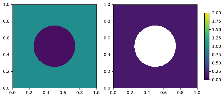
第一种方法在 DG0 空间求解质量矩阵方程 \(\int_\Omega f v=\int_{\Omega_{tag}} c v\), 得到在子区域 \(\Omega_{tag}\) 上取 \(c\)、其余区域取 0 的函数. 第二种方法用 dx(tag) 只遍历带相应标记的单元, 直接将其 DG0 自由度写为给定值. 示例使用 Poisson 方程 I 中带圆形界面的矩形网格, 区域编号 1 为圆外, 2 为圆内:
The first method solves the DG0 mass-matrix problem \(\int_\Omega f v=\int_{\Omega_{tag}} c v\), producing a function equal to \(c\) on the subdomain \(\Omega_{tag}\) and zero elsewhere. The second uses dx(tag) to iterate only over cells carrying the selected marker and writes the prescribed value directly to their DG0 degrees of freedom. The example uses the rectangular mesh with a circular interface from chapter Poisson I; tag 1 marks the exterior of the circle and tag 2 its interior:
from firedrake import *

from firedrake.pyplot import triplot, tricontourf
import matplotlib.pyplot as plt


# set marker function by solving equation
def make_marker_solve_equ(mesh, tag, value=1):
    V = FunctionSpace(mesh, 'DG', 0)

    u, v = TrialFunction(V), TestFunction(V)
    f = Function(V)
    solve(u*v*dx == Constant(value)*v*dx(tag) + Constant(0)*v*dx, f)
    return f


# set marker function by using par_loop
def make_marker_par_loop(mesh, tag, value=1):
    V = FunctionSpace(mesh, 'DG', 0)
    f = Function(V)
    domain = '{[i]: 0 <= i < A.dofs}'
    instructions = '''
    for i
        A[i] = {value}
    end
    '''
    # par_loop((domain, instructions.format(value=0)), dx, {'A' : (f, WRITE)})
    par_loop((domain, instructions.format(value=value)), dx(tag), {'A' : (f, WRITE)})
    return f
在带圆形界面的网格上, 分别构造圆外取 1 的 f1 和圆内取 2 的 f2. 为确认两种构造等价, 再用 par_loop 构造同样在圆外取 1 的 f1b, 并逐自由度比较 f1 与 f1b:
On the mesh with a circular interface, construct f1, equal to 1 outside the circle, and f2, equal to 2 inside it. To verify that the two constructions agree, build f1b with par_loop using the same value and exterior tag as f1, then compare their degrees of freedom:
mesh = Mesh('gmsh/circle_in_rect.msh')
f1 = make_marker_solve_equ(mesh, tag=1, value=1)
f2 = make_marker_par_loop(mesh, tag=2, value=2)

# the two methods give the same result for the same subdomain and value
f1b = make_marker_par_loop(mesh, tag=1, value=1)
same_values = np.allclose(f1.dat.data, f1b.dat.data)
assert same_values
print('f1 and f1b agree:', same_values)
f1 and f1b agree: True
下面并排画出 f1 和 f2. 两幅图共用取值范围 \([0,2]\) 和同一个色条, 以便看出两个函数都在未选中的子区域取 0:
Plot f1 and f2 side by side below. The two panels share the value range \([0,2]\) and a common color bar, making it clear that each function vanishes on the unselected subdomain:
from matplotlib import cm
from matplotlib import colormaps
from matplotlib.colors import Normalize

cmap = colormaps.get_cmap('viridis')
normalizer = Normalize(0, 2)
smap = cm.ScalarMappable(norm=normalizer, cmap=cmap)

fig, axes = plt.subplots(1, 2, figsize=[8, 4])
axes[0].set_aspect('equal')
axes[1].set_aspect('equal')
cs0 = tricontourf(f1, axes=axes[0], cmap=cmap, norm=normalizer)
cs1 = tricontourf(f2, axes=axes[1], cmap=cmap, norm=normalizer)

# fig.colorbar(smap, ax=axes.ravel().tolist())

pos = axes[1].get_position()
cbar_height = 0.8*pos.height
cbar_y0 = pos.y0 + 0.1*pos.height
cax = fig.add_axes([pos.x1 + 0.03, cbar_y0, 0.02, cbar_height])
cbar = fig.colorbar(smap, cax=cax)
2.5.2. 直接修改 dat.data Modifying dat.data directly#
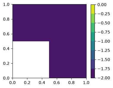
若已经知道本进程上的自由度编号, 也可以直接修改 f.dat.data. 下面在由 RectangleMesh(2, 2, 1, 1) 生成的单位正方形三角网格上构造 DG0 函数; 网格含 8 个三角形, 每个单元对应一个自由度. 代码先把所有本地自由度设为 \(-2\), 再把前两个改为 0, 最后画出所得分片常数函数. 这种方法依赖底层数据的本地编号, 并行时还要自行处理进程间的数据同步, 因而通常不如变分形式或 par_loop 稳健:
If the process-local dof numbers are already known, one may also modify f.dat.data directly. The example below constructs a DG0 function on the unit-square triangular mesh generated by RectangleMesh(2, 2, 1, 1); the mesh contains 8 triangles, with one degree of freedom per cell. The code first sets all local degrees of freedom to \(-2\), changes the first two to 0, and finally plots the resulting piecewise-constant function. This approach depends on the local numbering of the underlying data and requires explicit synchronization in parallel, so it is generally less robust than a variational form or par_loop:
from firedrake import *
from firedrake.pyplot import tricontourf
import matplotlib.pyplot as plt

mesh = RectangleMesh(2, 2, 1, 1)
V = FunctionSpace(mesh, 'DG', 0)
f = Function(V)
f.dat.data[:] = -2
f.dat.data[0:2] = 0

fig, ax = plt.subplots(figsize=[4, 4])
ax.set_aspect('equal')
cs = tricontourf(f, axes=ax)
cbar = fig.colorbar(cs, ax=ax, shrink=0.8)
2.6. Dirac delta 函数 Dirac delta functions#
2.6.1. 通过数值积分公式实现 Implementation via a quadrature rule#
点源 (Dirac delta 函数) \(\delta_{x_0}\) 满足 \(\int_\Omega \delta_{x_0} v = v(x_0)\). 借助 Poisson 方程 I 中的自定义积分公式, 可以把它实现为单点积分: 先用 locate_cell_and_reference_coordinate 找到 \(x_0\) 所在单元及参考坐标, 把积分点设在该参考坐标上, 再用只在该单元取 1 的指示函数把积分限制在这个单元内, 并把权重归一化, 便有 assemble(delta(f)) \(= f(x_0)\). 下面的 DiracOperator 实现了这一构造, 并处理了并行情形 (只有拥有 \(x_0\) 的进程贡献积分).
A point source (Dirac delta function) \(\delta_{x_0}\) satisfies \(\int_\Omega \delta_{x_0} v = v(x_0)\). With the custom quadrature rules of chapter Poisson I it can be implemented as a single-point quadrature: locate the cell containing \(x_0\) and its reference coordinate via locate_cell_and_reference_coordinate, place the quadrature point at that reference coordinate, restrict the integral to that cell by an indicator function, and normalize the weight, so that assemble(delta(f)) \(= f(x_0)\). The class DiracOperator below implements this construction and handles the parallel case (only the process owning \(x_0\) contributes).
from firedrake import *

from firedrake.petsc import PETSc
from pyop2 import op2
from pyop2.datatypes import ScalarType
from mpi4py import MPI
import finat
import numpy as np

import matplotlib.pyplot as plt

class DiracOperator(object):
    def __init__(self, m, x0):
        """Make Dirac delta operator at point

        Args:
            m: mesh
            x0: source point

        Example:
            delta = DiracOperator(m, x0)
            f = Function(V)
            f_x0 = assemble(delta(f))
        """
        self.mesh = m
        self.x0 = x0
        self.operator = None

    def __call__(self, f):
        if self.operator is None:
            self._init()
        return self.operator(f)

    def _init(self):
        m = self.mesh
        x0 = self.x0
        V = FunctionSpace(m, 'DG', 0)
        cell_marker = Function(V, name='cell_marker', dtype=ScalarType)
        qrule = finat.quadrature.make_quadrature(V.finat_element.cell, 0)
        cell, X = m.locate_cell_and_reference_coordinate(x0, tolerance=1e-6)

        # c = 0 if X is None else 1
        n_cell_local = len(cell_marker.dat.data)
        if X is not None and cell < n_cell_local:
            c = 1
        else:
            c = 0

        comm = m.comm
        s = comm.size - comm.rank
        n = comm.allreduce(int(s*c), op=MPI.MAX)

        if n == 0:
            raise BaseException("Points not found!")

        k = int(comm.size - n) # get the lower rank which include the point x0

        if c == 1 and comm.rank == k:
            X[X<0] = 0
            X[X>1] = 1
            cell_marker.dat.data[cell] = 1
            comm.bcast(X, root=k)
        else:
            cell_marker.dat.data[:] = 0 # we must set this otherwise the process will hangup
            X = comm.bcast(None, root=k)


        cell_marker.dat.global_to_local_begin(op2.READ)
        cell_marker.dat.global_to_local_end(op2.READ)

        qrule.point_set.points[0] = X
        qrule.weights[0] = qrule.weights[0]/np.real(assemble(cell_marker*dx))
        # Tell UFL that repr(qrule) is a stable signature for form caching.
        # Set it only after the quadrature point and weight have been updated.
        qrule.ufl_signature = repr(qrule)

        self.operator = lambda f: f*cell_marker*dx(scheme=qrule)
2.6.2. 测试 DiracOperator Testing DiracOperator#
分别在一维和二维网格上取光滑函数 \(g\), 用 PointEvaluator 计算 \(g(x_0)\), 再与 assemble(delta(g)) 比较:
On 1D and 2D meshes, take a smooth function \(g\), evaluate \(g(x_0)\) with PointEvaluator, and compare it with assemble(delta(g)):
def test_dirac_delta_1D():
    test_mesh = IntervalMesh(8, 1)
    V = FunctionSpace(test_mesh, 'CG', 3)
    x1 = 0.683
    source = Constant([x1,])
    delta = DiracOperator(test_mesh, source)

    x, = SpatialCoordinate(test_mesh)
    g = Function(V).interpolate(x**2)

    expected_value = PointEvaluator(test_mesh, [[x1]]).evaluate(g)[0]
    value = assemble(delta(g))
    assert np.isclose(value, expected_value)
    print('1D DiracOperator check passed.')


test_dirac_delta_1D()
1D DiracOperator check passed.
def test_dirac_delta_2D():
    test_mesh = RectangleMesh(8, 8, 1, 1)
    V = FunctionSpace(test_mesh, 'CG', 3)
    x1 = 0.683
    x2 = 0.333
    source = Constant([x1,x2])
    x0 = source
    delta = DiracOperator(test_mesh, source)

    x, y = SpatialCoordinate(test_mesh)
    g = Function(V).interpolate(x**3 + y**3)

    expected_value = PointEvaluator(test_mesh, [[x1, x2]]).evaluate(g)[0]
    value = assemble(delta(g))
    assert np.isclose(value, expected_value)
    print('2D DiracOperator check passed.')


test_dirac_delta_2D()
2D DiracOperator check passed.
2.6.3. Dirac delta 函数的 \(L^2\) 投影 \(L^2\) projection of the Dirac delta function#
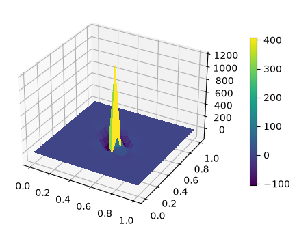
把 \(\delta_{x_0}\) “投影” 到有限元空间, 即求解 \(\int_\Omega u v = v(x_0)\). 注意 \(\delta_{x_0}\) 不属于 \(L^2\), 这个投影没有收敛意义: 所得函数在源点附近有很大的正负振荡, 且不随网格加密消失. 此例只是演示 DiracOperator 可以出现在变分形式的右端.
“Projecting” \(\delta_{x_0}\) onto a finite element space means solving \(\int_\Omega u v = v(x_0)\). Since \(\delta_{x_0}\) does not belong to \(L^2\), this projection has no convergence meaning: the resulting function exhibits large positive and negative oscillations near the source point that do not vanish under refinement. The example merely shows that a DiracOperator can appear on the right-hand side of a variational form.
N = 8
test_mesh = RectangleMesh(N, N, 1, 1)
V = FunctionSpace(test_mesh, 'CG', 3)
delta = DiracOperator(test_mesh, [0.51, 0.49])
bc = DirichletBC(V, 0, 'on_boundary')
u, v = TrialFunction(V), TestFunction(V)
sol = Function(V)
solve(u*conj(v)*dx == delta(conj(v)), sol, bcs=bc)

fig, ax = plt.subplots(figsize=[6, 4], subplot_kw=dict(projection='3d'))
ts = trisurf(sol, axes=ax)
cbar = fig.colorbar(ts, ax=ax, shrink=0.7, pad=0.1)
2.6.4. 求解源项为 Dirac delta 函数的 Poisson 方程 Poisson equation with a Dirac-delta source#
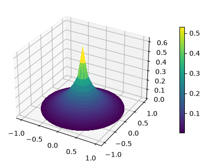
以 \(\delta_{x_0}\) 为源项求解 Poisson 方程, 得到的是 Green 函数的近似. 二维 Green 函数在源点处有对数奇性, 因此数值解在源点附近的值会随网格加密增大, 但在远离源点处仍然收敛.
Solving the Poisson equation with \(\delta_{x_0}\) as the source yields an approximation of the Green function. In 2D the Green function has a logarithmic singularity at the source, so the numerical solution grows near the source under refinement while still converging away from it.
x0 = [0, 0]
# N = 500
# m = SquareMesh(N, N, 1)

m = UnitDiskMesh(refinement_level=3)

V = FunctionSpace(m, 'CG', 1)

v = TestFunction(V)
u = TrialFunction(V)

a = inner(grad(u), grad(v))*dx
L = DiracOperator(m, x0)(v)
u = Function(V, name='u')

bc = DirichletBC(V, 0, 'on_boundary')

solve(a == L, u, bcs=bc)

# solve(a == L, u)
fig, ax = plt.subplots(figsize=[6, 4], subplot_kw=dict(projection='3d'))
ts = trisurf(u, axes=ax)
cbar = fig.colorbar(ts, ax=ax, shrink=0.7, pad=0.1)
2.7. 自适应有限元方法 Adaptive finite element methods#
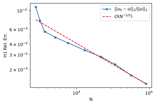
自适应方法按 “求解 → 误差估计 → 单元标记 → 网格加密” 的循环, 只加密误差大的单元, 用尽量少的自由度达到给定精度. 本节以 L 型区域上的 Poisson 问题为例给出完整流程, 网格加密通过 PETSc 的 DMPlex 完成.
PETSc 用 DMLabel 给 DMPlex 中的网格实体附加整数标记; adaptLabel 读取这些标记, 将相应实体解释为加密、粗化或保持不变, 并返回自适应后的 DMPlex. 在下面的 L 型区域算例中, mark_cells 把误差较大的单元写入名为 adapt 的标签, 随后由 plex.adaptLabel('adapt') 完成局部加密.
Adaptive methods iterate the loop “solve → estimate the error → mark cells → refine the mesh”, refining only where the error is large so as to reach a prescribed accuracy with as few degrees of freedom as possible. This section presents the complete workflow for the Poisson problem on an L-shaped domain; mesh refinement is carried out through PETSc’s DMPlex.
PETSc uses a DMLabel to attach integer markers to mesh entities in a DMPlex. adaptLabel reads those markers, interprets the corresponding entities as being refined, coarsened, or kept, and returns the adapted DMPlex. In the L-shaped example below, mark_cells writes cells with large errors to the label named adapt, after which plex.adaptLabel('adapt') performs the local refinement.
2.7.1. L 型区域上的 Poisson 自适应算例 Adaptive Poisson example on an L-shaped domain#
L 型区域的重入角使解在角点处有奇性, 均匀加密收敛缓慢, 是自适应方法的标准算例. 配套脚本 py/adapt_possion.py 依次实现以下步骤.
The re-entrant corner of the L-shaped domain makes the solution singular at the corner, so uniform refinement converges slowly — a standard test case for adaptivity. The companion script py/adapt_possion.py implements the following steps.
方程求解 Solving the equation
def solve_possion(mesh, u_handle, f_handle):
    x = SpatialCoordinate(mesh)
    u_e = u_handle(x)
    f = f_handle(x)

    V = FunctionSpace(mesh, 'CG', 1)
    u, v = TrialFunction(V), TestFunction(V)

    L = inner(f, v)*dx
    a = inner(grad(u), grad(v))*dx
    sol = Function(V, name='u_h')

    bc = DirichletBC(V, u_e, 'on_boundary')

    solve(a == L, sol, bcs=bc)

    err = errornorm(u_e, sol, norm_type='H1')/norm(u_e, norm_type='H1')

    return sol, err
误差估计 Error estimation
def estimate(mesh, sol, u_handle, f_handle, alpha, beta):
    x = SpatialCoordinate(mesh)
    u_e = u_handle(x)
    f = f_handle(x)

    V_eta_K = FunctionSpace(mesh, 'DG', 0)
    V_eta_e = FunctionSpace(mesh, 'HDivT', 0)

    phi_K = TestFunction(V_eta_K)
    phi_e = TestFunction(V_eta_e)

    phi = div(grad(sol)) + f
    g = jump(grad(sol), FacetNormal(mesh))

    ksi_K = assemble(inner(phi**2, phi_K)*dx)
    ksi_e = assemble(inner(g**2, avg(phi_e))*dS)
    ksi_outer = assemble(inner((sol-u_e)**2, phi_e)*ds)

    h_e = assemble(conj(phi_e)*ds)
    h_K = Function(V_eta_K).interpolate(CellDiameter(mesh))

    eta_K = assemble_eta_K_op2(ksi_K, ksi_e, ksi_outer, h_K, h_e, alpha=alpha, beta=beta)
    # eta_K2 = assemble_eta_K_py(ksi_K, ksi_e, ksi_outer, h_K, h_e, alpha=alpha, beta=beta)
    # assert np.allclose(eta_K.dat.data_ro_with_halos, eta_K2.dat.data_ro_with_halos)

    return eta_K
def assemble_eta_K_py(ksi_K, ksi_e, ksi_outer, h_K, h_e, alpha, beta):
    V_eta_K = ksi_K.function_space()
    V_eta_e = ksi_e.function_space()

    cell_node_list_K = V_eta_K.cell_node_list
    cell_node_list_e = V_eta_e.cell_node_list

    ne_per_cell = V_eta_e.cell_node_list.shape[1]

    s1 = np.zeros_like(ksi_K.dat.data_ro_with_halos)
    for i in range(0, ne_per_cell):
        s1 += ksi_e.dat.data_ro_with_halos[cell_node_list_e[:, i]]

    s2 = np.zeros_like(ksi_K.dat.data_ro_with_halos)
    for i in range(0, ne_per_cell):
        s2 += h_e.dat.data_ro_with_halos[cell_node_list_e[:, i]] * ksi_outer.dat.data_ro_with_halos[cell_node_list_e[:, i]]

    eta_K = Function(V_eta_K)
    eta_K.dat.data_with_halos[:] = np.sqrt(
        alpha * h_K.dat.data_ro_with_halos**2 * ksi_K.dat.data_ro_with_halos \
        + beta * h_K.dat.data_ro_with_halos * s1
        # + beta * (h_K.dat.data_ro_with_halos * s1 + s2)
    )

    return eta_K
网格标记 Marking cells
def mark_cells(mesh, eta_K, theta):
    plex = mesh.topology_dm
    cell_numbering = mesh._cell_numbering

    if plex.hasLabel('adapt'):
        plex.removeLabel('adapt')

    with eta_K.dat.vec_ro as vec:
        eta = vec.norm()
        eta_max = vec.max()[1]

    cell_node_list_K = eta_K.function_space().cell_node_list
    tol = theta*eta_max
    eta_K_data = eta_K.dat.data_ro_with_halos
    with PETSc.Log.Event("ADD_ADAPT_LABEL"):
        plex.createLabel('adapt')
        cs, ce = plex.getHeightStratum(0)
        for i in range(cs, ce):
            c = cell_numbering.getOffset(i)
            dof  = cell_node_list_K[c][0]
            if eta_K_data[dof] > tol:
                plex.setLabelValue('adapt', i, 1)

    return plex
使用以上函数以及 DMPlex 的 adaptLabel 方法, 就可以写出 L 型区域上的自适应求解循环:
Combining these functions with the adaptLabel method of DMPlex gives the adaptive loop on the L-shaped domain:
def adapt_possion_Lshape():
    om = OptionsManager({"dm_plex_transform_type": "refine_sbr"}, options_prefix='')

    def u_exact(x):
        mesh = x.ufl_domain()
        U = FunctionSpace(mesh, 'CG', 1)
        u = Function(U)
        coords = mesh.coordinates
        x1, x2 = np.real(coords.dat.data_ro[:, 0]), np.real(coords.dat.data_ro[:, 1])
        r = np.sqrt(x1**2 + x2**2)
        theta = np.arctan2(x2, x1)
        u.dat.data[:] = r**(2/3)*np.sin(2*theta/3)
        return u

    def f_handle(x):
        return Constant(0)

    mesh = Mesh('gmsh/Lshape.msh')
    result = []
    parameters = {}
    parameters["partition"] = False

    for i in range(10):
        if i != 0:
            eta_K = estimate(mesh, sol, u_exact, f_handle, alpha=0.15, beta=0.15)
            plex = mark_cells(mesh, eta_K, theta=0.2)

            with PETSc.Log.Event("ADAPT"):
                with om.inserted_options():
                    new_plex = plex.adaptLabel('adapt')
                # Remove labels to avoid errors
                new_plex.removeLabel('adapt')
                remove_pyop2_label(new_plex)

            new_plex.viewFromOptions('-dm_view')

            # mesh = Mesh(new_plex, distribution_parameters=parameters)
            mesh = Mesh(new_plex)

        sol, err = solve_possion(mesh, u_exact, f_handle)
        ndofs = sol.function_space().dim()
        result.append((ndofs, np.real(err)))

    return result
运行上述自适应循环, 画出误差随自由度数量的变化:
Run the adaptive loop above and plot the error against the number of degrees of freedom:
from py.adapt_possion import adapt_possion_Lshape, plot_adapt_result

result = adapt_possion_Lshape()
fig = plot_adapt_result(result)
2.7.2. 使用 adaptMetric 做度量驱动的网格自适应 Metric-based mesh adaptation with adaptMetric#
除了 adaptLabel, PETSc 还提供 adaptMetric 方法, 根据用户给定的度量场对网格自适应: 每个网格顶点对应一个度量矩阵 (以向量形式存储在 PETSc 的 local vector 中). 配套脚本为 py/test_adapt_metric.py.
流程为: 先用 create_metric_from_indicator 把标记函数 indicator 转化为度量场 v, 再用 to_petsc_local_numbering_for_local_vec 把自由度排序改为 PETSc 内部序, 最后调用 adaptMetric 完成自适应剖分.
Besides adaptLabel, PETSc provides the adaptMetric method, which adapts the mesh according to a user-supplied metric field: each mesh vertex carries a metric matrix (stored as a vector in a PETSc local vector). The companion script is py/test_adapt_metric.py.
The workflow is: convert the indicator function into a metric field v with create_metric_from_indicator, reorder the degrees of freedom into PETSc’s internal ordering with to_petsc_local_numbering_for_local_vec, and finally call adaptMetric to adapt the mesh.
def adapt(indicator):
    mesh = indicator.ufl_domain()
    metric = create_metric_from_indicator(indicator)
    v = PETSc.Vec().createWithArray(metric.dat._data,
                                    size=(metric.dat._data.size, None),
                                    bsize=metric.dat.cdim, comm=metric.comm)
    reordered = to_petsc_local_numbering_for_local_vec(v, metric.function_space())
    v.destroy()
    plex_new = mesh.topology_dm.adaptMetric(reordered, "Face Sets", "Cell Sets")
    mesh_new = Mesh(plex_new)

    return mesh_new
create_metric_from_indicator 构造度量场的思路是: 先逐单元计算度量矩阵, 再按单元体积加权平均得到顶点上的度量矩阵.
create_metric_from_indicator builds the metric field in two steps: compute the metric matrix cell by cell, then average onto the vertices with cell-volume weights.
对单元循环, 求解单元度量矩阵: Loop over the cells and solve for the cell metric:
82            pair.append([i, j])
83
84    for k, nodes in enumerate(Vc.cell_node_list):
85        vertex = coords[nodes, :]
86        edge = []
87        for i, j in pair:
88            edge.append(vertex[i, :] - vertex[j, :])
89
这里用到
edge2vec, 它把单元的边向量组装成计算度量矩阵所需的系数矩阵: Hereedge2vecassembles the edge vectors of a cell into the coefficient matrix used to compute the metric:67 68 dim = mesh.geometric_dimension 69 70 if dim == 2: 71 edge2vec = lambda e: [ e[0]**2, 2*e[0]*e[1], e[1]**2 ] 72 vec2tensor = lambda g: [[g[0], g[1]], [g[1], g[2]]] 73 elif dim == 3: 74 edge2vec = lambda e: [ e[0]**2, 2*e[0]*e[1], 2*e[0]*e[2], e[1]**2, 2*e[1]*e[2], e[2]**2 ]
根据单元体积加权平均, 得到顶点的度量矩阵: Average with cell-volume weights to obtain the vertex metrics:
91        for e in edge:
92            mat.append(edge2vec(e))
93
94        mat = np.array(mat)
95        b = np.ones(len(edge))
96        g = np.linalg.solve(mat, b)
97
to_petsc_local_numbering_for_local_vec 的内容如下: The function to_petsc_local_numbering_for_local_vec reads:
def to_petsc_local_numbering_for_local_vec(vec, V):
    section = V.dm.getLocalSection()
    out = vec.duplicate()
    varray = vec.array_r
    oarray = out.array
    dim = V.value_size
    idx = 0
    for p in range(*section.getChart()):
        dof = section.getDof(p)
        off = section.getOffset(p)
        # PETSc.Sys.syncPrint(f"dof = {dof}, offset = {off}")
        if dof > 0:
            off = section.getOffset(p)
            off *= dim
            for d in range(dof):
                for k in range(dim):
                    oarray[idx] = varray[off + dim * d + k]
                    idx += 1
    # PETSc.Sys.syncFlush()

    return out
通过命令行选项或 OptionsManager, 可以选择使用的自适应库 (pragmatic, mmg 或 parmmg): The adaptation library (pragmatic, mmg or parmmg) is selected via command-line options or an OptionsManager:
def test_adapt(dim=2, factor=2):
    if dim == 2:
        mesh = UnitSquareMesh(5, 5)
    elif dim == 3:
        mesh = UnitCubeMesh(5, 5, 5)
    else:
        raise Exception("")

    V = FunctionSpace(mesh, 'DG', 0)
    indicator = Function(V, name='indicator')
    indicator.dat.data[:] = factor
    mesh_adapt = adapt(indicator)

    mesh.topology_dm.viewFromOptions('-dm_view')
    mesh_adapt.topology_dm.viewFromOptions('-dm_view_new')
    return mesh, mesh_adapt
def test_adapt_with_option(dim=2, factor=0.5, adaptor=None):
    # adaptors: pragmatic, mmg, parmmg
    #   -dm_adaptor pragmatic
    #   -dm_adaptor mmg       # 2d or 3d (seq)
    #   -dm_adaptor parmmg    # 3d (parallel)

    adaptors = get_avaiable_adaptors()
    if adaptors is None:
        PETSc.Sys.Print("No adaptor found. You need to install pragmatic, mmg, or parmmg with petsc.")
        return None

    if adaptor is not None and adaptor not in adaptors:
        PETSc.Sys.Print(f"Adaptor {adaptor} not installed with petsc. Installed adaptors: {adaptors}.")
        return None

    if adaptor is None:
        adaptor = adaptors[0]

    parameters = {
        "dm_adaptor": adaptor,
        # "dm_plex_metric_target_complexity": 400,
        # "dm_view": None,
        # "dm_view_new": None,
    }

    om = OptionsManager(parameters, options_prefix="")
    with om.inserted_options():
        mesh, mesh_new = test_adapt(dim=dim, factor=factor)

    return mesh, mesh_new
下面展示三维立方体区域自适应的结果. 注意 Firedrake 官方镜像未安装 pragmatic, mmg, parmmg, 此时该单元将跳过计算:
Below is an adaptation result on a 3D cube. Note that pragmatic, mmg and parmmg are not installed in the official Firedrake image, in which case this cell skips the computation:
from py.test_adapt_metric import test_adapt, test_adapt_with_option
from py.intro_utils import triplot
import matplotlib.pyplot as plt

# adaptor: pragmatic, mmg, parmmg
# pragmatic, mmg, parmmg not installed in firedrake offcial docker image
ret = test_adapt_with_option(dim=3, factor=.3, adaptor="mmg")

if ret is not None:
    mesh, mesh_new = ret

    if mesh.geometric_dimension == 3:
        subplot_kw = dict(projection='3d')
    else:
        subplot_kw = {}
    fig, ax = plt.subplots(1, 2, figsize=[8, 3.5], subplot_kw=subplot_kw)
    tp = triplot(mesh, axes=ax[0])
    tp_new = triplot(mesh_new, axes=ax[1])
    t0 = ax[0].set_title('Original mesh')
    t1 = ax[1].set_title('Adapted mesh')
    fig.tight_layout()
No adaptor found. You need to install pragmatic, mmg, or parmmg with petsc.
2.7.3. 使用 adaptLabel 做全局网格变换 Global mesh transformations with adaptLabel#
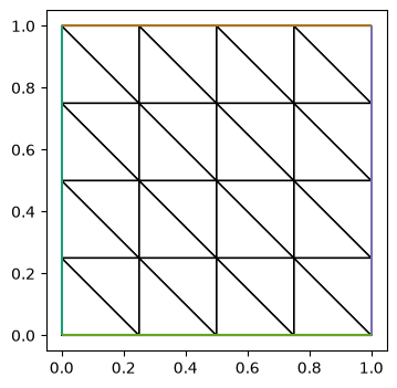
DM.adaptLabel 也可以脱离误差估计单独使用, 对整个网格做变换. 先构造网格并取出底层 plex:
DM.adaptLabel can also be used on its own, independently of error estimation, to transform the whole mesh. First build a mesh and extract the underlying plex:
from firedrake import RectangleMesh, Mesh
from py.intro_utils import triplot
# load original mesh
mesh = RectangleMesh(4, 4, 1, 1)
fig, ax = plt.subplots(figsize=[4, 4])
ax.set_aspect('equal')
c = triplot(mesh, axes=ax)
plex = mesh.topology_dm
# # or just read from gmsh file
# comm = COMM_WORLD
# plex = PETSc.DMPlex().createFromFile('mymesh.msh', comm)
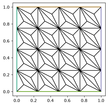
DMPlex 提供多种网格变换, 参考 Summary of Unstructured Mesh Transformations. 下面把变换类型设为 refine_alfeld, 做重心加密:
DMPlex offers a variety of mesh transformations; see the Summary of Unstructured Mesh Transformations. Below the transform type is set to refine_alfeld for barycentric refinement:
# Barycentric refinement for simplicies
# https://petsc.org/main/overview/plex_transform_table/
# opts = PETSc.Options()
# opts.insertString('-dm_plex_transform_type refine_alfeld') # can be set in command line
try:
    from petsctools.options import OptionsManager
except ImportError:
    from firedrake.petsc import OptionsManager

om = OptionsManager({"dm_plex_transform_type": "refine_alfeld"}, options_prefix='')
with om.inserted_options():
    new_plex = plex.adaptLabel(None)
new_mesh = Mesh(new_plex)
fig, ax = plt.subplots(figsize=[4, 4])
ax.set_aspect('equal')
c = triplot(new_mesh, axes=ax)
2.7.4. 更新 DMPlex 中的网格坐标 Updating mesh coordinates in DMPlex#
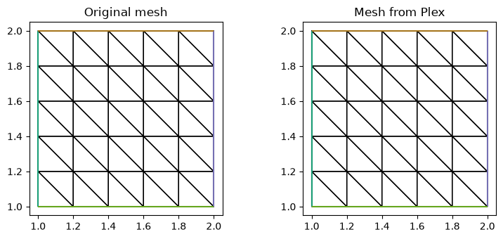
在 Firedrake 中修改网格坐标后 (例如移动网格), Firedrake 的坐标场已经更新, 但底层 DMPlex 仍保留原来的坐标, 因而两者不再一致. 若随后使用 DMPlex 做自适应加密, 需要先把更新后的 Firedrake 坐标同步到 DMPlex. 配套脚本 py/update_plex_coordinates.py 提供两种方式.
After mesh coordinates are modified in Firedrake (for example, by moving the mesh), Firedrake’s coordinate field is updated while the underlying DMPlex still retains the original coordinates, so the two no longer agree. Before using the DMPlex for subsequent adaptive refinement, the updated Firedrake coordinates must be synchronized to it. The companion script py/update_plex_coordinates.py offers two ways.
根据自由度的映射关系, 直接改写
plex的坐标: Rewrite theplexcoordinates directly using the dof maps:def get_plex_with_update_coordinates(mesh: MeshGeometry): """ Update the coordinates of the plex in mesh, and then return a clone without pyop2 label """ if hasattr(mesh.topology, 'init'): mesh.topology.init() dm = mesh.topology_dm.clone() csec = dm.getCoordinateSection() coords_vec = dm.getCoordinatesLocal() s, e = dm.getDepthStratum(0) sec = mesh._vertex_numbering data = mesh.coordinates.dat.data_ro_with_halos dest = np.zeros_like(data) n = mesh.geometric_dimension m = csec.getFieldComponents(0) assert m == n for i in range(s, e): # dof = sec.getDof(i) offset = sec.getOffset(i) # cdof = csec.getDof(i) coffset = csec.getOffset(i) dest[coffset//m] = data[offset, :] coords_vec.array_w[:] = dest.flatten() # dm.setCoordinatesLocal(coords_vec) remove_pyop2_label(dm) return dm
通过设置
Section的方式更新plex. 若使用的 Firedrake 包含 pr-2933, 可以使用该方式: Update theplexby setting aSection. This works for Firedrake versions that include pr-2933:def get_plex_with_update_coordinates_new(mesh: MeshGeometry): tdim = mesh.topological_dimension gdim = mesh.geometric_dimension entity_dofs = np.zeros(tdim + 1, dtype=np.int32) entity_dofs[0] = gdim coord_section = mesh.create_section(entity_dofs) plex = mesh.topology_dm.clone() coord_dm = plex.getCoordinateDM() coord_dm.setSection(coord_section) coords_local = coord_dm.createLocalVec() coords_local.array[:] = np.reshape( mesh.coordinates.dat.data_ro_with_halos, coords_local.array.shape ) plex.setCoordinatesLocal(coords_local) remove_pyop2_label(plex) return plex
Warning
对于不包含 pr-2933 的版本, 上述方法虽然可以更新坐标, 但是更新后的
plex不能作为Mesh的参数创建网格.Warning
For versions without pr-2933, this method still updates the coordinates, but the updated
plexcannot be passed toMeshto create a mesh.
下面移动网格后从更新过坐标的 plex 重建网格, 并与原网格对比:
Below, the mesh is moved, a new mesh is rebuilt from the plex with updated coordinates, and the two are compared:
from firedrake import *
from py.intro_utils import triplot
from py.update_plex_coordinates import \
    get_plex_with_update_coordinates, \
    get_plex_with_update_coordinates_new
import matplotlib.pyplot as plt

def save_mesh(mesh, name):
    V = FunctionSpace(mesh, 'CG', 1)
    f = Function(V, name='f')
    VTKFile(name).write(f)

mesh_init = RectangleMesh(5, 5, 1, 1)

# move mesh
mesh_init.coordinates.dat.data[:] += 1
save_mesh(mesh_init, 'pvd/mesh_init.pvd')

# recreate mesh from the plex
plex = get_plex_with_update_coordinates(mesh_init)
mesh = Mesh(plex, distribution_parameters={"partition": False})
save_mesh(mesh, 'pvd/mesh_with_update_plex.pvd')

fig, ax = plt.subplots(1, 2, figsize=[8, 3.5])
ax[0].set_aspect('equal')
ax[1].set_aspect('equal')
tp0 = triplot(mesh_init, axes=ax[0])
tp1 = triplot(mesh, axes=ax[1])
t0 = ax[0].set_title('Original mesh')
t1 = ax[1].set_title('Mesh from Plex')
fig.tight_layout()
2.8. 变分求解器的回调函数 Variational solver callbacks#
Firedrake 使用 PETSc 的 SNES 求解非线性问题 (线性问题也统一按非线性问题处理)
Firedrake solves nonlinear problems (linear problems are treated uniformly as nonlinear ones) with PETSc’s SNES:
并提供 4 个回调函数 pre_jacobian_callback, post_jacobian_callback, pre_function_callback, post_function_callback, 用于在组装前后修改 Jacobian (\(J = F'(x)\)) 和残差 \(F(x)\). 下面用一个最小示例演示 post_* 回调, 用户数据通过 appctx 传入:
and provides four callbacks — pre_jacobian_callback, post_jacobian_callback, pre_function_callback, post_function_callback — to modify the Jacobian (\(J = F'(x)\)) and the residual \(F(x)\) before or after assembly. The minimal example below demonstrates the post_* callbacks, with user data passed in through appctx:
from firedrake import *
from firedrake.petsc import PETSc
from functools import partial

mesh = UnitSquareMesh(4, 4)
V = FunctionSpace(mesh, 'CG', 1)
u, v = TrialFunction(V), TestFunction(V)
a = inner(grad(u), grad(v))*dx
L = v*dx
bc = DirichletBC(V, 0, 'on_boundary')

u_h = Function(V, name='u_h')
problem = LinearVariationalProblem(a, L, u_h, bcs=bc)


def post_jacobian_callback(X, J, appctx=None):
    # X: the current solution vector; J: the assembled Jacobian (PETSc Mat)
    #   https://petsc.org/main/petsc4py/reference/petsc4py.PETSc.Mat.html
    # Modify J here if needed, e.g. J.setValuesLocal(...); J.assemble()
    PETSc.Sys.Print('post_jacobian_callback:', appctx['msg'])


def post_function_callback(X, F, appctx=None):
    # X: the current solution vector; F: the assembled residual (PETSc Vec)
    #   https://petsc.org/main/petsc4py/reference/petsc4py.PETSc.Vec.html
    PETSc.Sys.Print(f'post_function_callback: |F| = {F.norm():.6e}')


appctx = {'msg': 'The msg from appctx'}
solver = LinearVariationalSolver(
    problem,
    post_jacobian_callback=partial(post_jacobian_callback, appctx=appctx),
    post_function_callback=partial(post_function_callback, appctx=appctx))
solver.solve()
post_function_callback: |F| = 1.875000e-01
post_jacobian_callback: The msg from appctx
一类实际用途是实现需要修改线性系统的特殊有限元方法. 例如完美导体问题 [LLY24]: 两个导体夹杂接近接触时, 解在夹缝内的梯度随夹杂间距趋于零而爆掉, 标准有限元空间无法一致逼近; 该文在梯度网格上引入一个解析构造的特殊基函数消解奇性, 需要把它并入标准组装得到的矩阵. 文中的实现是在组装后取出矩阵直接修改, 用这里的回调函数同样可以在每次组装后自动完成这类修改.
One practical use is implementing special finite element methods that modify the linear system. For the perfect conductivity problem [LLY24], for instance, the gradient of the solution in the narrow gap between two close-to-touching conductors blows up as the distance tends to zero, and standard finite element spaces cannot approximate it uniformly; that work introduces an analytically constructed special basis function on graded meshes to resolve the singularity, which has to be incorporated into the assembled matrix. The implementation in the paper extracts and modifies the matrix after assembly; the callbacks here can carry out the same kind of modification automatically after every assembly.
进阶: 并行运行与 Solver 内部 (点击展开)
并行运行时, 回调在每个进程上被调用; 用 PETSc.Sys.syncPrint 与 PETSc.Sys.syncFlush 可以按进程顺序查看各进程的输出 (并行运行方式见并行计算一章), 例如:
def post_jacobian_callback(X, J, appctx=None):
    rank, size = J.comm.rank, J.comm.size
    PETSc.Sys.syncPrint(f'  [{rank}/{size}] appctx: {appctx}')
    PETSc.Sys.syncFlush()
此外, 通过 solver._ctx 可以访问求解器内部的组装器和矩阵 (内部接口, 可能随版本变化):
ctx = solver._ctx
print('Assembler:', ctx._assembler_jac)
print('Matrix size:', ctx._jac.petscmat.getSizes())
Advanced: parallel runs and solver internals (click to expand)
In parallel the callbacks are invoked on every process; use PETSc.Sys.syncPrint with PETSc.Sys.syncFlush to inspect the output rank by rank (see the chapter on parallel computing for how to run in parallel), e.g.:
def post_jacobian_callback(X, J, appctx=None):
    rank, size = J.comm.rank, J.comm.size
    PETSc.Sys.syncPrint(f'  [{rank}/{size}] appctx: {appctx}')
    PETSc.Sys.syncFlush()
Moreover, solver._ctx gives access to the assembler and the matrix inside the solver (internal API, may change between versions):
ctx = solver._ctx
print('Assembler:', ctx._assembler_jac)
print('Matrix size:', ctx._jac.petscmat.getSizes())
2.9. 高振荡函数的插值误差 Interpolation error of highly oscillatory functions#
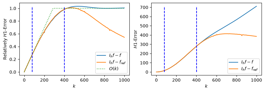
标准的一次 Lagrange 插值误差估计 [BS08] 为 \(\|I_h f-f\|_{H^1} \leq Ch|f|_{H^2}\). 对特征尺度为 \(1/k\) 的光滑振荡函数, 二阶导数相对一阶导数多带一个 \(k\), 因而可写成
The standard error estimate for linear Lagrange interpolation [BS08] is \(\|I_h f-f\|_{H^1} \leq Ch|f|_{H^2}\). For a smooth oscillatory function with characteristic scale \(1/k\), a second derivative contributes one additional factor of \(k\) relative to a first derivative, and hence
即在 \(kh\) 较小时, 相对插值误差随 \(k\) 线性增长; 网格不能分辨波长后, 误差逐渐饱和. 高频 Helmholtz 问题中波数显式的有限元逼近条件与误差分析可参考 [MS11]. 下面固定网格 (\(N = 64\)), 把 \(k\) 从 0 扫到 1000, 计算插值的相对与绝对 \(H^1\) 误差; 参考函数取 \(p+2\) 次空间中的插值. 图中竖线分别标出每个波长 5 个和 1 个网格点对应的 \(k\) 值.
Thus, while \(kh\) is small, the relative interpolation error grows linearly with \(k\); once the mesh can no longer resolve the wavelength, the error gradually saturates. For wavenumber-explicit finite element approximation conditions and error analysis for high-frequency Helmholtz problems, see [MS11]. Below, on a fixed mesh (\(N = 64\)), \(k\) is swept from 0 to 1000 and the relative and absolute \(H^1\) errors of the interpolant are computed, with the reference taken as the interpolant in the degree-\((p+2)\) space. The vertical lines mark the values of \(k\) corresponding to 5 and 1 mesh points per wavelength.
from firedrake import *
import numpy as np
import matplotlib.pyplot as plt

def get_H1_expr(e):
    return (inner(e, e) + inner(grad(e), grad(e)))*dx

N = 64
mesh = RectangleMesh(N, N, 1, 1)
h = 1/N

x = SpatialCoordinate(mesh)
k = Constant(1)
f = cos(k*sqrt(dot(x,x)))

p = 1
V = FunctionSpace(mesh, 'CG', p)
V_ref = FunctionSpace(mesh, 'CG', p+2)

Int = interpolate(f, V)
Int_ref = interpolate(f, V_ref)

f_int = Function(V)
f_ref = Function(V_ref)

e = f_int - f
e_ref = f_int - f_ref

f_H1 = get_H1_expr(f)
f_ref_H1 = get_H1_expr(f_ref)
f_int_H1 = get_H1_expr(f_int)
e_H1 = get_H1_expr(e)
e_ref_H1 = get_H1_expr(e_ref)

ks = np.linspace(0, 1000, 200)
errors = np.zeros((len(ks), 2))

dtype = np.dtype([
    ('k', 'f8'),
    ('f_H1', 'f8'),
    ('f_ref_H1', 'f8'),
    ('f_int_H1', 'f8'),
    ('e_H1', 'f8'),
    ('e_ref_H1', 'f8'),
])

ret = np.zeros(len(ks), dtype=dtype)

for i, _k in enumerate(ks):
    k.assign(_k)
    assemble(Int, tensor=f_int)
    assemble(Int_ref, tensor=f_ref)
    a = sqrt(assemble(f_H1)), sqrt(assemble(f_ref_H1)), sqrt(assemble(f_int_H1))
    b = sqrt(assemble(e_H1)), sqrt(assemble(e_ref_H1))
    ret[i] = (_k, *a, *b)
tsfc:WARNING Estimated quadrature degree 22 more than tenfold greater than any argument/coefficient degree (max 1)
tsfc:WARNING Estimated quadrature degree 22 more than tenfold greater than any argument/coefficient degree (max 1)
fig, axes = plt.subplots(1, 2, figsize=[10, 3])
e_H1_rel = ret['e_H1']/ret['f_H1']
e_ref_H1_rel = ret['e_ref_H1']/ret['f_H1']
axes[0].plot(ret['k'], e_H1_rel, label='$I_h f - f$')
axes[0].plot(ret['k'], e_ref_H1_rel, label='$I_h f - f_{ref}$')

ref_line = e_H1_rel[10]*ret['k']/ret['k'][10]
ref_line[ref_line>1] = 1
axes[0].plot(ret['k'], ref_line, ':', label='$O(k)$')

upper = max(e_H1_rel.max(), e_ref_H1_rel.max())
for n in (1, 5):
    k_max = 2*pi/(n*h)
    axes[0].plot([k_max, k_max], [0, upper], 'b--')
axes[0].set_xlabel('$k$')
axes[0].set_ylabel('Relatively $H1$-Error')
axes[0].legend()

axes[1].plot(ret['k'], ret['e_H1'], label='$I_h f - f$')
axes[1].plot(ret['k'], ret['e_ref_H1'], label='$I_h f - f_{ref}$')
upper = max(ret['e_H1'].max(), ret['e_ref_H1'].max())
for n in (1, 5):
    k_max = 2*pi/(n*h)
    axes[1].plot([k_max, k_max], [0, upper], 'b--')
axes[1].set_xlabel('$k$')
axes[1].set_ylabel('$H1$-Error')
axes[1].legend()

# axes[0].set_xlim([0, 50])
# axes[0].set_ylim([0, 0.4])
# axes[1].set_xlim([-10, 50])
<matplotlib.legend.Legend at 0x7fdad6a98fb0>
References
Martin Sandve Alnæs, Anders Logg, and Kent-Andre Mardal. UFC: a finite element code generation interface, pages 283–302. Springer Berlin Heidelberg, 2012. doi:10.1007/978-3-642-23099-8_16.
Douglas N. Arnold. An interior penalty finite element method with discontinuous elements. SIAM Journal on Numerical Analysis, 19(4):742–760, 1982. doi:10.1137/0719052.
Douglas N. Arnold, Franco Brezzi, Bernardo Cockburn, and L. Donatella Marini. Unified analysis of discontinuous Galerkin methods for elliptic problems. SIAM Journal on Numerical Analysis, 39(5):1749–1779, 2002. doi:10.1137/S0036142901384162.
Susanne C. Brenner and L. Ridgway Scott. The Mathematical Theory of Finite Element Methods. Volume 15 of Texts in Applied Mathematics. Springer, New York, 3 edition, 2008. ISBN 978-0-387-75934-0. doi:10.1007/978-0-387-75934-0.
Yekaterina Epshteyn and Béatrice Rivière. Estimation of penalty parameters for symmetric interior penalty Galerkin methods. Journal of Computational and Applied Mathematics, 206(2):843–872, 2007. doi:10.1016/j.cam.2006.08.029.
M. Lenoir. Optimal isoparametric finite elements and error estimates for domains involving curved boundaries. SIAM Journal on Numerical Analysis, 23(3):562–580, jun 1986. doi:10.1137/0723036.
Buyang Li, Haigang Li, and Zongze Yang. Convergent finite element methods for the perfect conductivity problem with close-to-touching inclusions. IMA Journal of Numerical Analysis, 44(6):3280–3312, 2024. doi:10.1093/imanum/drad088.
Jens M. Melenk and Stefan A. Sauter. Wavenumber explicit convergence analysis for galerkin discretizations of the helmholtz equation. SIAM Journal on Numerical Analysis, 49(3):1210–1243, 2011. doi:10.1137/090776202.
Dominik Schötzau, Christoph Schwab, and Andrea Toselli. Mixed hp-DGFEM for incompressible flows. SIAM Journal on Numerical Analysis, 40(6):2171–2194, 2003. doi:10.1137/S0036142901399124.
Khosro Shahbazi. An explicit expression for the penalty parameter of the interior penalty method. Journal of Computational Physics, 205(2):401–407, 2005. doi:10.1016/j.jcp.2004.11.017.