6. DMPlex 和 Mesh DMPlex and Mesh#
DMPlex 的基本用法参见 DMPlex.
For the basic usage of DMPlex see DMPlex.
概要
Firedrake 的网格如何用 PETSc 的 DMPlex 表示: DMPlex 的创建、PETSc.Section、DMPlex 与 Firedrake Mesh/FunctionSpace 的关系, 以及几何实体的定位与节点编号.
Overview
How Firedrake meshes are represented by PETSc DMPlex: creating a DMPlex, PETSc.Section, the relation between DMPlex and Firedrake Mesh/FunctionSpace, and locating geometric entities and their DoF numbering.
本章的示例大多会跑两遍: 一遍在 notebook 自己的串行内核里, 一遍通过 ipyparallel
在 2 个 MPI 进程上跑 (后者的代码单元以 %%px 开头). 这样安排是因为 DMPlex 的实体编号、core/owned/ghost 分类和 node_set 的大小只有在网格被分区之后才显出差别,
串行的结果只是并行结果的退化情形.
先启动一个 2 进程的 MPI 集群.
Most of the examples in this chapter are run twice: once in the notebook’s own
serial kernel, and once on 2 MPI processes through ipyparallel (the code cells of
the latter begin with %%px). This is done because the DMPlex entity numbering,
the core/owned/ghost classification and the size of node_set only start to
differ once the mesh has been partitioned; the serial results are merely the
degenerate case of the parallel ones.
First start an MPI cluster with 2 processes.
import ipyparallel as ipp

cluster = ipp.Cluster(engines="mpi", n=2)
client = cluster.start_and_connect_sync()
Starting 2 engines with <class 'ipyparallel.cluster.launcher.MPIEngineSetLauncher'>
%%px 是 ipyparallel 提供的 cell magic, 表示这个单元的代码在集群的每个引擎 (即每个
MPI 进程) 上各执行一遍, --block 让 notebook 等所有引擎跑完再继续. 引擎有自己独立的命名空间, 所以要单独 import 一次.
%%px is a cell magic provided by ipyparallel; it means that the code of this
cell is executed once on every engine of the cluster (one engine per MPI
process), and --block makes the notebook wait until all the engines have
finished before continuing. The engines have their own separate namespaces, so
the imports have to be done there once more.
%%px --block
from firedrake import *
from firedrake.petsc import PETSc
from mpi4py import MPI
import numpy as np
在串行环境中导入必要的包
Import the necessary packages in the serial environment.
from firedrake import *
from firedrake.petsc import PETSc
from mpi4py import MPI
import numpy as np
6.1. 创建 DMPlex Creating a DMPlex#
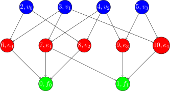
DMPlex 把网格里所有维度的几何实体 (顶点、边、面、单元) 统一编号成”点” (point), 再用 cone (某个点的直接边界) 和 support (直接包含某个点的实体) 记录它们之间的覆盖关系. 整体是一张有向无环图, 也就是下面第二张图里的 Hasse 图.
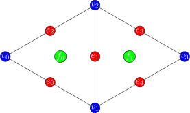
下面两张 PETSc 官方插图画的是 doublet 网格: 两个共享一条边的三角形, 共 2 个单元、 5 条边、4 个顶点, 一共 11 个点. 图中同一维度的实体占据连续的一段编号: 0-1 是单元, 2-5 是顶点, 6-10 是边.
DMPlex numbers the geometric entities of all dimensions in a mesh (vertices, edges, faces and cells) uniformly as “points”, and records the covering relations between them with the cone (the immediate boundary of a point) and the support (the entities that immediately contain a point). The whole thing is a directed acyclic graph: the Hasse diagram in the second figure below.
The two official PETSc figures below show the doublet mesh: two triangles sharing an edge, with 2 cells, 5 edges and 4 vertices, 11 points in total. In the figures the entities of the same dimension occupy a contiguous range of numbers: 0-1 are the cells, 2-5 the vertices and 6-10 the edges.
6.1.1. 底层创建方法 The low-level construction#
手工构造一个 DMPlex 的步骤是: 先用 setChart 声明一共有多少个点, 再用 setConeSize
给每个点声明它的 cone 有多大 (三角形有 3 条边, 边有 2 个顶点, 顶点没有 cone, 保持默认的 0 即可), 最后 setUp 分配存储. 下面按上图的编号构造出那张 doublet 网格.
Building a DMPlex by hand goes as follows: first declare with setChart how many
points there are in total, then declare with setConeSize how large the cone of
every point is (a triangle has 3 edges, an edge has 2 vertices, a vertex has no
cone and can keep the default 0), and finally allocate the storage with setUp.
Below the doublet mesh is built with the numbering of the figure above.
plex = PETSc.DMPlex().create()
plex.setDimension(2)
plex.setChart(0, 11)
# plex.setConeSize(point, number of points that cover the point)
plex.setConeSize(0, 3)
plex.setConeSize(1, 3)
plex.setConeSize(6, 2)
plex.setConeSize(7, 2)
plex.setConeSize(8, 2)
plex.setConeSize(9, 2)
plex.setConeSize(10, 2)
plex = plex.setUp()  # plex.setUp() return self
接着用 setCone 逐点填入覆盖关系: 每个三角形给出它的 3 条边, 每条边给出它的 2 个顶点. symmetrize() 由 cone 反算出 support, stratify() 计算每个点的 depth (顶点为 0、边为 1、单元为 2). view() 的输出里应看到 4 个 0-cells、5 个 1-cells、
2 个 2-cells, 与上图一致.
Next the covering relations are filled in point by point with setCone: every
triangle is given its 3 edges and every edge its 2 vertices. symmetrize()
computes the supports back from the cones, and stratify() computes the depth of
every point (0 for vertices, 1 for edges, 2 for cells). The output of view()
should show 4 0-cells, 5 1-cells and 2 2-cells, in agreement with the figure
above.
# plex.setCone(point, [points that cover the point])
plex.setCone(0, [6, 7, 8])
plex.setCone(1, [7, 9, 10])
plex.setCone(6, [2, 3])
plex.setCone(7, [3, 4])
plex.setCone(8, [4, 2])
plex.setCone(9, [4, 5])
plex.setCone(10, [5, 3])

plex.symmetrize()
plex.stratify()

plex.view()
DM Object: 1 MPI process
  type: plex
DM_0x33f29730_0 in 2 dimensions:
  Number of 0-cells per rank: 4
  Number of 1-cells per rank: 5
  Number of 2-cells per rank: 2
Labels:
  depth: 3 strata with value/size (0 (4), 1 (5), 2 (2))
  celltype: 3 strata with value/size (0 (4), 1 (5), 3 (2))
6.1.2. 使用高级接口 Using the high-level interfaces#
下面用 createFromCellList 重建同一张 doublet 网格: 只需给出 2 个三角形各自的顶点编号和 4 个顶点的坐标, interpolate=True 让 PETSc 自动补出中间的边. view() 报出的点数和各维实体个数与上面手工构造的完全一致 (两段输出在 DM Object: 的名字和
Labels: 的排列顺序上有出入, 不必在意).
Below createFromCellList is used to rebuild the same doublet mesh: it is enough
to give the vertex numbers of the 2 triangles and the coordinates of the 4
vertices, and interpolate=True lets PETSc create the intermediate edges
automatically. The number of points and the number of entities of each dimension
reported by view() are exactly the same as for the mesh built by hand above
(the two outputs differ in the name under DM Object: and in the order of the
entries under Labels:, which does not matter).
cells = [
    [0, 1, 2],
    [1, 3, 2]
]
coords = [
    [-1, 0],
    [0, -1],
    [0, 1],
    [1, 0]
]

plex = PETSc.DMPlex().createFromCellList(
    dim=2, cells=cells, coords=coords, interpolate=True, comm=None)

plex.view()
DM Object: DM_0x33f29730_1 1 MPI process
  type: plex
DM_0x33f29730_1 in 2 dimensions:
  Number of 0-cells per rank: 4
  Number of 1-cells per rank: 5
  Number of 2-cells per rank: 2
Labels:
  celltype: 3 strata with value/size (0 (4), 1 (5), 3 (2))
  depth: 3 strata with value/size (0 (4), 1 (5), 2 (2))
6.2. PETSc.Section#
PETSc.Section 描述的是”每个点上放几个自由度、放在数据数组的什么位置”, 是从拓扑
(DMPlex) 到数据布局之间的桥梁. 下面建两个 Section 做对照: section1 用默认顺序,
section2 额外设一个排列 (permutation), 看同样的自由度在两种顺序下 offset 有什么不同.
PETSc.Section describes “how many degrees of freedom sit on every point and
where they are placed in the data array”; it is the bridge from the topology
(DMPlex) to the data layout. Two Sections are built below for comparison:
section1 uses the default order, while section2 additionally sets a
permutation, so that one can see how the offsets of the same degrees of freedom
differ between the two orders.
section1 = PETSc.Section().create()
section1.setChart(*plex.getChart())
section2 = PETSc.Section().create()
section2.setChart(*plex.getChart())
这里用 RCM (反向 Cuthill-McKee) 算一个重排. 注意方向: getOrdering 返回的是
old_to_new, 而 setPermutation 要的是反过来的 reordering[new]->[old], 因此先用一次索引赋值把它求逆.
Here RCM (reverse Cuthill-McKee) is used to compute a reordering. Mind the
direction: getOrdering returns old_to_new, whereas setPermutation expects
the opposite reordering[new]->[old], so it is first inverted by one indexed
assignment.
old_to_new = plex.getOrdering(PETSc.Mat.OrderingType.RCM).indices
reordering = np.empty_like(old_to_new)  # reordering[new] -> old
reordering[old_to_new] = np.arange(old_to_new.size, dtype=old_to_new.dtype)

perm = PETSc.IS().createGeneral(reordering)
section2.setPermutation(perm)
只给顶点 (depth 为 0 的点) 各放 1 个自由度, 两个 Section 放得完全一样; setUp()
之后 offset 才被算出来.
Only the vertices (the points of depth 0) are given 1 degree of freedom each, and
the two Sections are given exactly the same ones; the offsets are computed only
after setUp().
ps, pe = plex.getDepthStratum(0)
for p in range(ps, pe):
    section1.addDof(p, 1)
    section2.addDof(p, 1)

section1.setUp()
section2.setUp()
对比两个 Section 的输出: dof 都是点 2-5 上各 1 个, 其余点为 0; 但 section1 的
offset 依次是 0、1、2、3, section2 因为设了排列变成 3、0、2、1. 可见 permutation
改变的是数据在数组里的存放次序, 不改变每个点上有多少自由度.
Compare the output of the two Sections: in both of them the dof is 1 on each of
the points 2-5 and 0 on the remaining points; but the offsets of section1 are
0, 1, 2, 3 in order, while those of section2 become 3, 0, 2, 1 because of the
permutation that was set. One sees that the permutation changes the order in
which the data are stored in the array, not how many degrees of freedom sit on
each point.
section1.view()
section2.view()
PetscSection Object: 1 MPI process
  type not yet set
Process 0:
  (   0) dof  0 offset   0
  (   1) dof  0 offset   0
  (   2) dof  1 offset   0
  (   3) dof  1 offset   1
  (   4) dof  1 offset   2
  (   5) dof  1 offset   3
  (   6) dof  0 offset   4
  (   7) dof  0 offset   4
  (   8) dof  0 offset   4
  (   9) dof  0 offset   4
  (  10) dof  0 offset   4
PetscSection Object: 1 MPI process
  type not yet set
Process 0:
  (   0) dof  0 offset   0
  (   1) dof  0 offset   0
  (   2) dof  1 offset   3
  (   3) dof  1 offset   0
  (   4) dof  1 offset   2
  (   5) dof  1 offset   1
  (   6) dof  0 offset   4
  (   7) dof  0 offset   4
  (   8) dof  0 offset   4
  (   9) dof  0 offset   4
  (  10) dof  0 offset   4
6.3. Firedrake 中的 Mesh Mesh in Firedrake#
Firedrake 的 Mesh 内部持有一个 DMPlex, 用 mesh.topology_dm 就能拿到. 但 Firedrake
并不直接沿用 DMPlex 的点编号, 而是重新编一套: 一方面按 RCM 重排以改善数据局部性,
另一方面要把本进程可见的点按 PyOP2 的三个类别分成连续的三段.
三个类别的判据是 (以 dmcommon.mark_entity_classes 的实现为准):
ghost: DMPlex point SF 的 leaf, 即本进程的影子点, 实际归别的进程所有;
owned: 本身不是 ghost, 但它所在的某个本地单元的闭包里含有 ghost 点;
core: 其余的点, 即本进程拥有、且周围一圈单元的闭包里都没有影子点.
这样分是为了让计算和通信重叠: core 上的计算不碰任何影子数据, 可以在 halo 交换还没完成时就先算; owned 上的计算必须等交换结束. core + owned 就是”本进程持有”的部分,
ghost 不算在内.
顺带一提, mark_entity_classes 的 docstring 把 core/owned 描述成”是否在 send halo
里”, 和上面的实现并不一致: 实测存在被标为 core、却同时落在别的进程影子区里的点.
读源码时以实现为准.
Firedrake’s Mesh holds a DMPlex internally, which can be obtained with
mesh.topology_dm. But Firedrake does not reuse the point numbering of the
DMPlex directly; it makes a numbering of its own: on the one hand the points are
reordered by RCM to improve data locality, on the other hand the points visible
to this process have to be split into three contiguous ranges according to
PyOP2’s three classes.
The criteria of the three classes are (following the implementation of
dmcommon.mark_entity_classes):
ghost: a leaf of the DMPlex point SF: a ghost point of this process, actually owned by another process;
owned: not a ghost itself, but lying in the closure of some local cell whose closure contains a ghost point;
core: the remaining points, those owned by this process whose surrounding cells have no ghost point in their closures.
The purpose of this split is to overlap computation and communication: the
computation on the core points touches no ghost data and can start before the
halo exchange has finished, while the computation on the owned points must wait
for the exchange to end. core + owned is the part “owned by this process”; the
ghost points are not counted in.
Incidentally, the docstring of mark_entity_classes describes core/owned in
terms of “being in the send halo”, which does not agree with the implementation
above: in practice there are points that are marked core and at the same time lie
in the halo of another process. When reading the source, follow the
implementation.
mesh = RectangleMesh(4, 4, 1, 1)
plex = mesh.topology_dm
rank, size = mesh.comm.rank, mesh.comm.size
同一张网格在 2 个进程上再建一次. 引擎的命名空间和 notebook 内核是分开的, 因此 import 和建网格都要重做一遍; 这一次网格会被分成两块, 每个进程只拿到自己那块外加一圈影子区.
The same mesh is built once more on 2 processes. The namespace of the engines is separate from that of the notebook kernel, so both the imports and the mesh construction have to be redone; this time the mesh is split into two pieces, and every process only gets its own piece plus a surrounding halo.
%%px --block
from firedrake import *
from firedrake.petsc import PETSc
from mpi4py import MPI

mesh = RectangleMesh(4, 4, 1, 1)
plex = mesh.topology_dm
rank, size = mesh.comm.rank, mesh.comm.size
mesh._dm_renumbering 就是上面说的那套编号, 类型是 PETSc.IS, 含义为
indices[新编号] = 原 DMPlex 点号. 每个进程只列出自己看得见的点 (含影子区), 因此两个进程各自的长度都小于串行时的总点数; 数组从前到后依次是 core、owned、ghost 三段.
mesh._dm_renumbering is exactly the numbering described above; its type is
PETSc.IS and its meaning is indices[new number] = original DMPlex point number. Every process only lists the points it can see (halo included), so the
length on either process is smaller than the total number of points in the serial
case; from front to back the array consists of the three ranges core, owned and
ghost.
%%px --block
mesh._dm_renumbering.indices
Out[1:3]:
array([ 0, 39, 57, 47, 21, 23, 20,  1, 61, 49, 24,  2, 40, 48,  4, 41, 58,
       26,  3, 50,  5, 62, 51, 27,  6, 42,  8, 43, 59, 29,  7, 52,  9, 63,
       53, 30, 10, 44, 12, 45, 60, 32, 11, 54, 13, 64, 55, 33, 14, 46, 15,
       56, 22, 65, 25, 66, 28, 67, 31, 68, 34, 16, 69, 73, 35, 17, 70, 74,
       36, 18, 71, 75, 37, 19, 72, 76, 38], dtype=int32)
Out[0:3]:
array([15, 46, 64, 56, 27, 29, 14, 54, 11, 44, 63, 25, 10, 52,  7, 42, 62,
       23,  6, 50,  3, 40, 61, 21,  2, 48, 28, 60, 26, 13, 45, 55, 12, 53,
       59, 24,  9, 43,  8, 51, 58, 22,  5, 41,  4, 49, 57, 20,  1, 39,  0,
       47, 38, 19, 68, 76, 72, 37, 36, 18, 67, 75, 71, 35, 34, 17, 66, 74,
       70, 33, 32, 73, 30, 16, 65, 69, 31], dtype=int32)
和重新编号相关的函数 (位于 firedrake/mesh.py 和 firedrake/cython/dmcommon.pyx)
MeshTopology._default_reordering: RCM 重排,_default_reordering[new]->[old]; 由topology_dm.getOrdering(RCM)求逆得到, 只管数据局部性, 不管并行分类.MeshTopology._dm_renumbering: 最终使用的实体编号,_dm_renumbering[new]->[old]; 在 RCM 的基础上再按 core/owned/ghost 分块.MeshTopology._renumber_entities: 上面两步的入口;reorder=False时跳过 RCM, 直接按 DMPlex 原始顺序遍历.dmcommon.mark_entity_classes: 检查 DMPlex 的 point SF, 给每个点打上pyop2_core、pyop2_owned、pyop2_ghost之一的 label.dmcommon.get_entity_classes: 把这三个 label 统计成每个维度的累积分界数组, 即mesh._entity_classes.dmcommon.plex_renumbering: 真正生成排列的地方, 返回的PETSc.IS满足indices[PyOP2 实体号] = DMPlex 点号, 与第 2 条同向. 它只按 RCM 顺序把单元遍历 一遍, 对每个单元闭包里尚未编号的点查它属于哪一类, 再用 core/owned/ghost 三个各自独立的写游标写进对应的一段 —— 三段因此各自连续, 并不是把网格遍历三遍.
Functions related to the renumbering (in firedrake/mesh.py and
firedrake/cython/dmcommon.pyx)
MeshTopology._default_reordering: the RCM reordering,_default_reordering[new]->[old]; obtained by invertingtopology_dm.getOrdering(RCM), it only cares about data locality, not about the parallel classification.MeshTopology._dm_renumbering: the entity numbering that is actually used,_dm_renumbering[new]->[old]; on top of RCM it further groups the points by core/owned/ghost.MeshTopology._renumber_entities: the entry point of the two steps above; withreorder=Falsethe RCM step is skipped and the points are traversed in the original DMPlex order.dmcommon.mark_entity_classes: inspects the point SF of the DMPlex and gives every point one of the labelspyop2_core,pyop2_ownedandpyop2_ghost.dmcommon.get_entity_classes: turns these three labels into the array of cumulative boundaries per dimension,mesh._entity_classes.dmcommon.plex_renumbering: the place where the permutation is really produced; the returnedPETSc.ISsatisfiesindices[PyOP2 entity number] = DMPlex point number, the same direction as in item 2. It traverses the cells in RCM order once only; for every point of a cell closure that is not numbered yet it looks up which class the point belongs to, and writes it into the corresponding range with three independent write cursors for core/owned/ghost — this is why the three ranges are each contiguous, and not because the mesh is traversed three times.
下面把 mesh._default_reordering 和手工算出来的 RCM 排列并排打印, 两者应当完全一致,
说明 _default_reordering 就是对本进程的 DMPlex 调用 getOrdering(RCM) 再求逆.
它和 _dm_renumbering 不同 —— 后者在此基础上还按 core/owned/ghost 分了块.
Below mesh._default_reordering and a hand-computed RCM permutation are printed
side by side; the two should agree exactly, showing that _default_reordering is
just getOrdering(RCM) called on the DMPlex of this process and then inverted.
It differs from _dm_renumbering — the latter further groups the points by
core/owned/ghost on top of it.
%%px --block
# https://petsc.org/release/manualpages/DMPlex/DMPlexGetOrdering
old_to_new = plex.getOrdering(PETSc.Mat.OrderingType.RCM).indices
reordering = np.empty_like(old_to_new)
reordering[old_to_new] = np.arange(old_to_new.size, dtype=old_to_new.dtype)
mesh._default_reordering, reordering
Out[1:4]:
(array([ 0,  1,  2, 16,  4,  3,  5,  6, 17,  8,  7,  9, 10, 18, 12, 11, 13,
        14, 15, 19, 21, 23, 20, 24, 22, 35, 25, 26, 27, 36, 28, 29, 30, 37,
        31, 32, 33, 34, 38, 39, 57, 47, 61, 49, 40, 48, 69, 65, 73, 41, 58,
        50, 62, 51, 42, 70, 66, 74, 43, 59, 52, 63, 53, 44, 71, 67, 75, 45,
        60, 54, 64, 55, 46, 68, 56, 72, 76], dtype=int32),
 array([ 0,  1,  2, 16,  4,  3,  5,  6, 17,  8,  7,  9, 10, 18, 12, 11, 13,
        14, 15, 19, 21, 23, 20, 24, 22, 35, 25, 26, 27, 36, 28, 29, 30, 37,
        31, 32, 33, 34, 38, 39, 57, 47, 61, 49, 40, 48, 69, 65, 73, 41, 58,
        50, 62, 51, 42, 70, 66, 74, 43, 59, 52, 63, 53, 44, 71, 67, 75, 45,
        60, 54, 64, 55, 46, 68, 56, 72, 76], dtype=int32))
Out[0:4]:
(array([15, 14, 13, 19, 11, 12, 10,  9, 18,  7,  8,  6,  5, 17,  3,  4,  2,
         1,  0, 16, 27, 28, 29, 26, 38, 36, 37, 25, 24, 34, 35, 23, 22, 32,
        33, 21, 20, 30, 31, 46, 64, 56, 60, 54, 45, 55, 68, 76, 72, 44, 63,
        53, 59, 52, 43, 67, 75, 71, 42, 62, 51, 58, 50, 41, 66, 74, 70, 40,
        61, 49, 57, 48, 39, 73, 47, 65, 69], dtype=int32),
 array([15, 14, 13, 19, 11, 12, 10,  9, 18,  7,  8,  6,  5, 17,  3,  4,  2,
         1,  0, 16, 27, 28, 29, 26, 38, 36, 37, 25, 24, 34, 35, 23, 22, 32,
        33, 21, 20, 30, 31, 46, 64, 56, 60, 54, 45, 55, 68, 76, 72, 44, 63,
        53, 59, 52, 43, 67, 75, 71, 42, 62, 51, 58, 50, 41, 66, 74, 70, 40,
        61, 49, 57, 48, 39, 73, 47, 65, 69], dtype=int32))
这个单元先 view() 出 DMPlex. 并行时它只打印一份: Number of ...-cells per rank:
那几行按进程逐个列出实体个数, 而紧随其后 Labels: 里的
pyop2_core: 1 strata with value/size (1 (...)) 等只是 0 号进程的数字, 不是全局总量, 也不是别的进程的数字. 这三个 pyop2_* label 就是 mark_entity_classes 打上去的.
接着打印 mesh._entity_classes, 它是逐进程的. 每行对应一个维度的实体 (第 0 行是顶点,
第 1 行是边, 第 2 行是单元), 三个数是累积分界, 即
[core 数, core+owned 数, 三类总数]. 串行时没有影子区, 三个数相等.
This cell first view()s the DMPlex. In parallel it only prints one copy: the
lines Number of ...-cells per rank: list the number of entities process by
process, whereas the entries under the Labels: that follows, such as
pyop2_core: 1 strata with value/size (1 (...)), are only the numbers of
process 0; they are neither a global total nor the numbers of another process.
These three pyop2_* labels are the ones set by mark_entity_classes.
Then mesh._entity_classes is printed, which is per process. Every row
corresponds to the entities of one dimension (row 0 the vertices, row 1 the
edges, row 2 the cells), and the three numbers are cumulative boundaries,
[number of core, number of core+owned, total of the three classes]. In
serial there is no halo, so the three numbers are equal.
%%px --block
mesh.topology_dm.view()
entity_classes = mesh._entity_classes
ec_msg = ', '.join([f'{i}-cells: {ec}' for i, ec in enumerate(entity_classes)])
PETSc.Sys.syncPrint(f'[{rank}/{size}] mesh._entity_classes (core, owned, ghost): {ec_msg}')
PETSc.Sys.syncFlush()
[stdout:0] DM Object: DM_0x29380350_0 2 MPI processes
  type: plex
DM_0x29380350_0 in 2 dimensions:
  Number of 0-cells per rank: 19 19
  Number of 1-cells per rank: 38 38
  Number of 2-cells per rank: 20 20
Labels:
  depth: 3 strata with value/size (0 (19), 1 (38), 2 (20))
  celltype: 3 strata with value/size (0 (19), 1 (38), 3 (20))
  marker: 1 strata with value/size (1 (19))
  Face Sets: 3 strata with value/size (2 (9), 3 (5), 4 (7))
  exterior_facets: 1 strata with value/size (1 (19))
  interior_facets: 1 strata with value/size (1 (47))
  pyop2_core: 1 strata with value/size (1 (26))
  pyop2_owned: 1 strata with value/size (1 (26))
  pyop2_ghost: 1 strata with value/size (1 (25))
[0/2] mesh._entity_classes (core, owned, ghost): 0-cells: [ 5 10 19], 1-cells: [13 26 38], 2-cells: [ 8 16 20]
[1/2] mesh._entity_classes (core, owned, ghost): 0-cells: [10 15 19], 1-cells: [26 30 38], 2-cells: [16 16 20]
计算 node_set 相关的函数 (位于 firedrake/functionspacedata.py、firedrake/mesh.py、
firedrake/cython/dmcommon.pyx 和 firedrake/halo.py)
functionspacedata.get_node_set: 汇合下面几项, 组装出 PyOP2 的节点集合node_set.functionspacedata.get_global_numbering: 取得 (必要时新建) 描述节点布局的PETSc.Section, 也就是后面用到的V.global_numbering. 注意它返回的是(Section, 受约束节点数)二元组,V.global_numbering是其中的第一项.AbstractMeshTopology.create_section: 网格一侧的入口, 转手调用下一项, 同样返回上述二元组 (它自己的 docstring 只写了 Section, 不准).dmcommon.create_section: 按nodes_per_entity给每个 DMPlex 点分配自由度个数和 offset, 生成上述 Section.firedrake.Halo: 用 DMPlex 的 point SF 和这个 Section 构造影子区的通信结构.make_dofs_per_plex_entity:MeshTopology的方法, 把有限元的entity_dofs压成 “每个维度的实体各带几个节点”, 即nodes_per_entity.
Functions involved in computing node_set (in
firedrake/functionspacedata.py, firedrake/mesh.py,
firedrake/cython/dmcommon.pyx and firedrake/halo.py)
functionspacedata.get_node_set: brings the items below together and assembles PyOP2’s node setnode_set.functionspacedata.get_global_numbering: obtains (and creates if necessary) thePETSc.Sectionthat describes the node layout, theV.global_numberingused later. Note that it returns the pair(Section, number of constrained nodes), of whichV.global_numberingis the first item.AbstractMeshTopology.create_section: the entry point on the mesh side, which forwards to the next item and likewise returns the pair above (its own docstring only mentions the Section, which is inaccurate).dmcommon.create_section: assigns to every DMPlex point a number of degrees of freedom and an offset according tonodes_per_entity, producing the Section above.firedrake.Halo: builds the communication structure of the halo from the point SF of the DMPlex and this Section.make_dofs_per_plex_entity: a method ofMeshTopologythat compresses theentity_dofsof a finite element into “how many nodes the entities of each dimension carry” —nodes_per_entity.
计算 node_set 相关的概念
entity_dofs(FIATFIAT/finite_element.py): 参考单元上”哪个实体带哪几个局部自由度”的映射, 通过V.finat_element.entity_dofs()取到.nodes_per_entity(firedrake/functionspacedata.py): 把entity_dofs压成按维度计的节点数元组, 是create_section的直接输入.
Concepts involved in computing node_set
entity_dofs(FIAT,FIAT/finite_element.py): the map on the reference cell of “which entity carries which local degrees of freedom”, obtained throughV.finat_element.entity_dofs().nodes_per_entity(firedrake/functionspacedata.py): compressesentity_dofsinto a tuple of node counts per dimension; it is the direct input ofcreate_section.
把这两个概念打印出来对照. CG1 只在顶点上有自由度, 所以 nodes_per_entity 是
(1, 0, 0); CG2 在顶点和边上各有一个, 是 (1, 1, 0). 元组的三个位置依次对应顶点、
边、单元.
Print the two of them and compare. CG1 has degrees of freedom on the vertices
only, so its nodes_per_entity is (1, 0, 0); CG2 has one on each vertex and
one on each edge, which gives (1, 1, 0). The three positions of the tuple
correspond to vertices, edges and cells in this order.
V1 = FunctionSpace(mesh, 'CG', 1)
V2 = FunctionSpace(mesh, 'CG', 2)
PETSc.Sys.Print(f'V1 entity_dofs: {V1.finat_element.entity_dofs()}')
PETSc.Sys.Print(f'V2 entity_dofs: {V2.finat_element.entity_dofs()}')
nodes_per_entity_V1 = tuple(mesh.make_dofs_per_plex_entity(V1.finat_element.entity_dofs()))
nodes_per_entity_V2 = tuple(mesh.make_dofs_per_plex_entity(V2.finat_element.entity_dofs()))
PETSc.Sys.Print(f'V1 nodes_per_entity: {nodes_per_entity_V1}')
PETSc.Sys.Print(f'V2 nodes_per_entity: {nodes_per_entity_V2}')
V1 entity_dofs: {0: {0: [0], 1: [1], 2: [2]}, 1: {2: [], 1: [], 0: []}, 2: {0: []}}
V2 entity_dofs: {0: {0: [0], 1: [3], 2: [5]}, 1: {2: [1], 1: [2], 0: [4]}, 2: {0: []}}
V1 nodes_per_entity: (1, 0, 0)
V2 nodes_per_entity: (1, 1, 0)
同一段代码在 2 个进程上跑一遍. entity_dofs 和 nodes_per_entity 只取决于有限元本身, 与网格如何分区无关, 所以并行的输出和串行完全一样; 这里用的 PETSc.Sys.Print
只在 0 号进程打印, 因此每行仍只出现一次.
The same piece of code run on 2 processes. entity_dofs and nodes_per_entity
depend only on the finite element itself and not on how the mesh is partitioned,
so the parallel output is exactly the same as the serial one; the
PETSc.Sys.Print used here prints on process 0 only, so every line still appears
just once.
%%px --block
V1 = FunctionSpace(mesh, 'CG', 1)
V2 = FunctionSpace(mesh, 'CG', 2)
PETSc.Sys.Print(f'V1 entity_dofs: {V1.finat_element.entity_dofs()}')
PETSc.Sys.Print(f'V2 entity_dofs: {V2.finat_element.entity_dofs()}')
nodes_per_entity_V1 = tuple(mesh.make_dofs_per_plex_entity(V1.finat_element.entity_dofs()))
nodes_per_entity_V2 = tuple(mesh.make_dofs_per_plex_entity(V2.finat_element.entity_dofs()))
PETSc.Sys.Print(f'V1 nodes_per_entity: {nodes_per_entity_V1}')
PETSc.Sys.Print(f'V2 nodes_per_entity: {nodes_per_entity_V2}')
[stdout:0] V1 entity_dofs: {0: {0: [0], 1: [1], 2: [2]}, 1: {2: [], 1: [], 0: []}, 2: {0: []}}
V2 entity_dofs: {0: {0: [0], 1: [3], 2: [5]}, 1: {2: [1], 1: [2], 0: [4]}, 2: {0: []}}
V1 nodes_per_entity: (1, 0, 0)
V2 nodes_per_entity: (1, 1, 0)
node_set 是 PyOP2 用来描述
“本进程有哪些节点”的集合, 它的分类正是从 mesh._entity_classes 来的. 下面打印两个容易混淆的尺寸: node_set.size 是本进程持有的节点数, 也就是 core + owned;
而 V.node_count 还把影子区算在内, 两者不要混用. 两个进程的 size 加起来等于全局节点数; 对 CG1 而言, size 恰好等于上面 _entity_classes 第 0 行的第 2 个数.
node_set is the set with which PyOP2 describes “which nodes this process
has”, and its classification comes precisely from mesh._entity_classes. Two easily confused
sizes are printed below: node_set.size is the number of nodes owned by this
process (core + owned), whereas V.node_count also includes the halo; the two must not be mixed up. The sizes of the two processes add up to the
global number of nodes; for CG1, size is exactly the second number in row 0 of
the _entity_classes above.
%%px --block
PETSc.Sys.syncPrint(f'[{rank}/{size}] V1 node_set.size (owned): {V1.node_set.size}, '
                    f'node_count (with halo): {V1.node_count}')
PETSc.Sys.syncFlush()
[stdout:0] [0/2] V1 node_set.size (owned): 10, node_count (with halo): 19
[1/2] V1 node_set.size (owned): 15, node_count (with halo): 19
6.4. FunctionSpace#
一个 FunctionSpace 的自由度布局由 FunctionSpaceData (即
V._shared_data) 缓存, 其中 global_numbering 就是上一节那种 PETSc.Section,
node_set 是 PyOP2 的节点集合; dof_dset 在其上再包一层 DMShell, 供 PETSc 一侧使用. 这几个对象的引用关系如下.
下图使用 Sphinx / Jupyter Book 图形插件 plantuml 制作.
The degree-of-freedom layout of a FunctionSpace is cached by
FunctionSpaceData (V._shared_data), in which global_numbering is a
PETSc.Section of the kind seen in the previous section and node_set is
PyOP2’s node set; dof_dset wraps one more DMShell
around it for use on the PETSc side. The references between these objects are as
follows.
The figure below is made with plantuml, one of the graphics plugins for Sphinx / Jupyter Book.
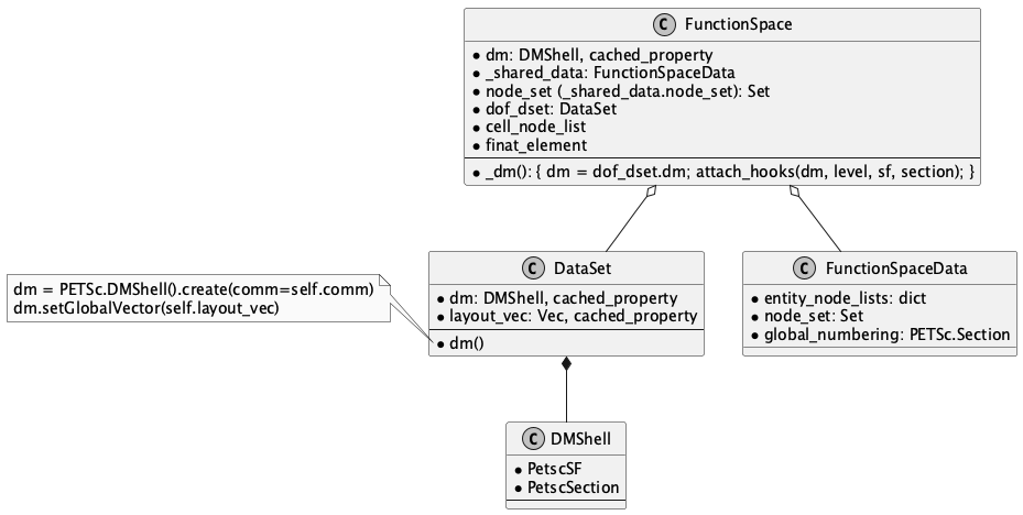
Fig. 6.1 class FunctionSpace#
6.5. 示例: 寻找特定的几何实体以及节点编号 Example: locating specific geometric entities and their node numbering#
这一节解决一个具体问题: 已知 gmsh 打的物理标签, 如何在 DMPlex
里定位到对应的边或面, 再把 DMPlex 的点号翻译成 Firedrake 的节点编号, 从而能直接去
Function 的数据数组里读取这些点上的值. 翻译这一步靠的就是 V.global_numbering
这个 PETSc.Section: getOffset(点号) 给出该点上第一个节点在本进程数据数组中的下标.
并行时还多一件事: 同一个实体可能同时出现在几个进程的影子区里, 因此要用 pyop2_core
和 pyop2_owned 两个 label 把它筛给唯一的持有者, 否则会被重复处理.
This section solves a concrete problem: given the physical tags set in gmsh,
how to locate the corresponding edges or faces in the DMPlex, and then translate the DMPlex point numbers into
Firedrake node numbers, so that the values at these points can be read directly
from the data array of a Function. This last translation relies on the
PETSc.Section V.global_numbering: getOffset(point number) gives the index
of the first node on that point in the data array of this process.
In parallel there is one more thing to do: the same entity may appear in the halo
of several processes at once, so the two labels pyop2_core and pyop2_owned
are used to filter it down to its unique owner; otherwise it would be processed
more than once.
6.5.1. 二维示例 Two-dimensional example#
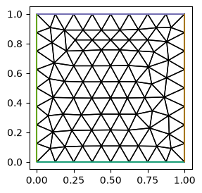
使用 global_numbering 寻找某条边界上的端点, 以及在这条边界上与它相邻的点 (2D mesh)
网格 gmsh/rectangle.msh 的四条边界在 gmsh/rectangle.geo 里各打了一个物理标签:
1 是下边界, 2 是上边界, 3 是左边界, 4 是右边界. 载入后这些标签落在 DMPlex 的
Face Sets label 上 —— 在下面 topology_dm.view() 的输出里可以看到
Face Sets: 4 strata.
Using global_numbering to find an end point on a given boundary, together with
the point adjacent to it on that boundary (2D mesh)
Each of the four boundaries of the mesh gmsh/rectangle.msh is given a physical
tag in gmsh/rectangle.geo: 1 is the bottom boundary, 2 the top one, 3 the left
one and 4 the right one. After loading, these tags end up on the Face Sets
label of the DMPlex — Face Sets: 4 strata can be seen in the output of
topology_dm.view() below.
from firedrake import *
from py.intro_utils import triplot
import matplotlib.pyplot as plt
import numpy as np

rectangle = Mesh("gmsh/rectangle.msh")
fig, axes = plt.subplots(figsize=[4, 3])
triplot(rectangle, axes=axes)
axes.set_aspect('equal')
rectangle.topology_dm.view()
DM Object: firedrake_default_topology 1 MPI process
  type: plex
firedrake_default_topology in 2 dimensions:
  Number of 0-cells per rank: 98
  Number of 1-cells per rank: 259
  Number of 2-cells per rank: 162
Labels:
  celltype: 3 strata with value/size (0 (98), 1 (259), 3 (162))
  depth: 3 strata with value/size (0 (98), 1 (259), 2 (162))
  Cell Sets: 1 strata with value/size (1 (162))
  Face Sets: 4 strata with value/size (1 (17), 2 (17), 3 (17), 4 (17))
  exterior_facets: 1 strata with value/size (1 (64))
  interior_facets: 1 strata with value/size (1 (325))
  pyop2_core: 1 strata with value/size (1 (519))
  pyop2_owned: 0 strata with value/size ()
  pyop2_ghost: 0 strata with value/size ()
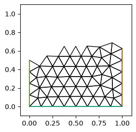
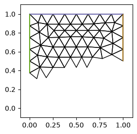
并行版本. 网格被分成两块, 每个进程只画自己分到的那部分; 这里额外固定了坐标轴范围, 方便和串行的图对照.
The parallel version. The mesh is split into two pieces and every process only draws the piece it received; the axis limits are additionally fixed here to make the comparison with the serial figure easier.
%%px --block
from firedrake import *
from py.intro_utils import triplot
import matplotlib.pyplot as plt
import numpy as np

rectangle = Mesh("gmsh/rectangle.msh")
fig, axes = plt.subplots(figsize=[4, 3])
triplot(rectangle, axes=axes)
axes.set_aspect('equal')
axes.set_xlim([-0.1, 1.1])
axes.set_ylim([-0.1, 1.1])
rectangle.topology_dm.view()
[stdout:0] DM Object: firedrake_default_topology 2 MPI processes
  type: plex
firedrake_default_topology in 2 dimensions:
  Number of 0-cells per rank: 61 60
  Number of 1-cells per rank: 150 149
  Number of 2-cells per rank: 90 90
Labels:
  depth: 3 strata with value/size (0 (61), 1 (150), 2 (90))
  celltype: 3 strata with value/size (0 (61), 1 (150), 3 (90))
  Cell Sets: 1 strata with value/size (1 (90))
  Face Sets: 3 strata with value/size (2 (17), 3 (11), 4 (9))
  exterior_facets: 1 strata with value/size (1 (35))
  interior_facets: 1 strata with value/size (1 (194))
  pyop2_core: 1 strata with value/size (1 (190))
  pyop2_owned: 1 strata with value/size (1 (60))
  pyop2_ghost: 1 strata with value/size (1 (51))
[output:1]
[output:0]
下面这个函数做三件事. 第一, 用 Face Sets label 分别取出两条边界上的点 —— Firedrake
从 gmsh 载入时会把物理曲线上的边连同它的端点一起打上标签, 因此两个集合的交集
(np.intersect1d) 恰好是这两条边界的公共角点. 第二, 在这个角点的 support (所有以它为端点的边) 里挑一条既属于目标边界、又是本进程 core 或 owned 的边, 这条边的 cone 给出另一个端点. 第三, 用 V.global_numbering.getOffset 把两个 DMPlex 点号换成 Firedrake
的节点号, 拿去 coordinates.dat 里取坐标.
串行这一次取的是 tag 1 (下边界) 和 tag 3 (左边界), 得到的是角点 (0, 0) 以及它在下边界上的邻点. 注意取坐标的 rectangle.coordinates.dat.data_ro_with_halos 写在 if 外面:
它是集合操作, 只让一部分进程调用会把程序挂住.
还有一个容易被忽略的前提: getOffset 给出的是该函数空间自己的节点下标, 拿它去索引坐标数组, 只在 V 是 CG1 时才成立 —— CG1 的节点与网格顶点一一对应, 编号也一致.
换成 CG2 就不再成立: 实测同一个顶点在 CG2 下的 offset 是 134, 而这张网格的坐标数组只有 98 个元素, 直接索引会 IndexError. 要按几何位置取值, 应当用坐标场自己的函数空间的编号.
The function below does three things. First, it takes the points of the two
boundaries out of the Face Sets label — when loading from gmsh, Firedrake tags
the edges of a physical curve together with their end points, so the intersection
of the two sets (np.intersect1d) is exactly the corner point shared by the two
boundaries. Second, among the support of that corner point (all the edges having
it as an end point) it picks an edge that belongs to the target boundary and is
core or owned on this process; the cone of that edge gives the other end point.
Third, V.global_numbering.getOffset turns the two DMPlex point numbers into
Firedrake node numbers, which are used to fetch the coordinates from
coordinates.dat.
In serial, tag 1 (the bottom boundary) and tag 3 (the left boundary) are taken
this time, which gives the corner point (0, 0) and its neighbor on the bottom
boundary. Note that rectangle.coordinates.dat.data_ro_with_halos, which fetches
the coordinates, is written outside the if: it is a collective operation, and
letting only some of the processes call it would hang the program.
There is one more easily overlooked precondition: the index given by getOffset
is a node index of that function space itself, and using it to index the
coordinate array is only valid when V is CG1 — the nodes of CG1 are in
one-to-one correspondence with the mesh vertices and are numbered alike. It no
longer holds for CG2: in practice the offset of the same vertex under CG2 is 134,
whereas the coordinate array of this mesh has only 98 entries, so indexing it
directly gives an IndexError. To read values by geometric position one should
use the numbering of the function space of the coordinate field itself.
def get_interface_element_with_contact_point(mesh, V, interface_tag, adj_line_tag):
    dm = mesh.topology_dm
    edge_label = dm.getLabel("Face Sets")  # 2D Face is Edge
    core_label = dm.getLabel("pyop2_core")
    owned_label = dm.getLabel("pyop2_owned")

    edge_label_values = edge_label.getValueIS().indices
    interface_indices = []
    if interface_tag in edge_label_values:
        interface_indices = edge_label.getStratumIS(interface_tag).indices

    adj_line = []
    if adj_line_tag in edge_label_values:
        adj_line = edge_label.getStratumIS(adj_line_tag).indices

    points = np.intersect1d(interface_indices, adj_line)

    plex_element = []
    if len(points) > 0:
        point = points[0]
        support = dm.getSupport(point)
        for edge in support:
            if edge_label.getValue(edge) == interface_tag and \
                (core_label.getValue(edge) == 1 or owned_label.getValue(edge) == 1):
                cone = dm.getCone(edge)
                adj_point = cone[1] if cone[0] == point else cone[0]
                plex_element = [point, adj_point]
                break

    local_section = V.global_numbering  # global_numbering is a local section
    element = [local_section.getOffset(_) for _ in plex_element]

    return element

# Face Sets tags of gmsh/rectangle.msh: 1 lower, 2 upper, 3 left, 4 right
V = FunctionSpace(rectangle, 'CG', 1)
element = get_interface_element_with_contact_point(rectangle, V, interface_tag=1, adj_line_tag=3)
coords_data = rectangle.coordinates.dat.data_ro_with_halos  # This must be outside the if condition (mpi collective)

rank, size = rectangle.comm.rank, rectangle.comm.size
if len(element) > 0:
    coords = [coords_data[_] for _ in element]
    PETSc.Sys.syncPrint(f"[{rank}/{size}] node {element[0]}: {coords[0]}), node {element[1]}: {coords[1]}")
PETSc.Sys.syncFlush()
[0/1] node 41: [0. 0.]), node 47: [0.125 0. ]
并行版本换成 tag 2 (上边界) 和 tag 4 (右边界), 找的是角点 (1, 1). 2 进程下只有一个进程打印出一行, 另一个进程的 element 是空的.
原因不在 core/owned 判断, 而在分区: 这一次的分区把上边界整块分给了其中一个进程,
另一个进程的 Face Sets 里压根没有 tag 2 这个值, interface_indices 是空的,
np.intersect1d 直接得到空集, 于是 if len(points) > 0 之下的代码一次都没执行.
分区是会变的 —— 改进程数, 甚至只是改变本次会话中建网格的先后顺序, 有输出的就可能换成另一个进程. 因此不要把”哪个进程有输出”当成固定结论.
core_label / owned_label 那个判断解决的是另一个问题: 同一条边可能同时出现在几个进程的影子区里, 有了这个条件才能保证它只被唯一的持有者处理, 结果不会随进程数翻倍. 本例进程数少, 角点周围那几条边恰好全是 core, 因此这个条件一条也没筛掉 —— 在这个单元里真正起筛选作用的是同一行的
edge_label.getValue(edge) == interface_tag, 它把角点 support 里的内部边和另一条边界上的边排除掉了.
The parallel version uses tag 2 (the top boundary) and tag 4 (the right boundary)
instead, and looks for the corner point (1, 1). On 2 processes only one of them
prints a line; the element of the other process is empty.
The reason is not the core/owned test but the partitioning: the partitioning
obtained this time gave the whole top boundary to one of the processes, and the
Face Sets of the other process does not contain the value 2 at all, so that its
interface_indices is empty, np.intersect1d directly gives an empty set, and
the code under if len(points) > 0 is never executed. The partitioning does
change — changing the number of processes, or even just the order in which the
meshes are built in this session, may make the other process the one that
produces output. So do not take “which process produces output” as a fixed
conclusion.
The core_label / owned_label test solves a different problem: the same edge
may appear in the halo of several processes at once, and only with this condition is it guaranteed to be handled by its unique
owner, so that the result does not double with the number of processes. There are
few processes in this example, and the few edges around the corner point happen
to be all core, so this condition filters out nothing at all — what really
filters in this cell is edge_label.getValue(edge) == interface_tag on the same
line, which excludes the interior edges in the support of the corner point and
the edges on the other boundary.
%%px --block
def get_interface_element_with_contact_point(mesh, V, interface_tag, adj_line_tag):
    dm = mesh.topology_dm
    edge_label = dm.getLabel("Face Sets")  # 2D Face is Edge
    core_label = dm.getLabel("pyop2_core")
    owned_label = dm.getLabel("pyop2_owned")

    edge_label_values = edge_label.getValueIS().indices
    interface_indices = []
    if interface_tag in edge_label_values:
        interface_indices = edge_label.getStratumIS(interface_tag).indices

    adj_line = []
    if adj_line_tag in edge_label_values:
        adj_line = edge_label.getStratumIS(adj_line_tag).indices

    points = np.intersect1d(interface_indices, adj_line)

    plex_element = []
    if len(points) > 0:
        point = points[0]
        support = dm.getSupport(point)
        for edge in support:
            if edge_label.getValue(edge) == interface_tag and \
                (core_label.getValue(edge) == 1 or owned_label.getValue(edge) == 1):
                cone = dm.getCone(edge)
                adj_point = cone[1] if cone[0] == point else cone[0]
                plex_element = [point, adj_point]
                break

    local_section = V.global_numbering  # global_numbering is a local section
    element = [local_section.getOffset(_) for _ in plex_element]

    return element

# Face Sets tags of gmsh/rectangle.msh: 1 lower, 2 upper, 3 left, 4 right

V = FunctionSpace(rectangle, 'CG', 1)
element = get_interface_element_with_contact_point(rectangle, V, interface_tag=2, adj_line_tag=4)
coords_data = rectangle.coordinates.dat.data_ro_with_halos  # This must be outside the if condition (mpi collective)

rank, size = rectangle.comm.rank, rectangle.comm.size
if len(element) > 0:
    coords = [coords_data[_] for _ in element]
    PETSc.Sys.syncPrint(f"[{rank}/{size}] node {element[0]}: {coords[0]}), node {element[1]}: {coords[1]}")
PETSc.Sys.syncFlush()
[stdout:0] [0/2] node 32: [1. 1.]), node 29: [0.875 1. ]
6.5.2. 三维示例 Three-dimensional example#
使用 global_numbering 寻找界面上与接触线相邻的三角形 (3D mesh)
本示例网格文件 cylinder.msh 由几何文件 cylinder.geo 生成,
如图:
Using global_numbering to find the triangles on an interface that are adjacent
to the contact line (3D mesh)
The mesh file cylinder.msh of this example is generated
from the geometry file cylinder.geo, as in the
figure:
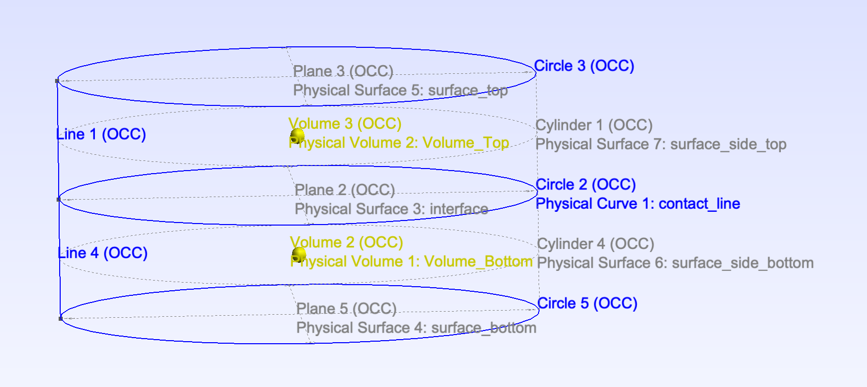
这是上下两块拼起来的圆柱, 交界面在 z = 0.25 处. 交界面的物理标签是 3 (interface),
它的圆周边界线标签是 1 (contact_line). 载入后, 一维的物理曲线落在 DMPlex 的
Edge Sets label 上, 二维的物理曲面落在 Face Sets 上.
This is a cylinder made of two blocks stacked together, with the interface at
z = 0.25. The physical tag of the interface is 3 (interface) and the tag of its
circular boundary line is 1 (contact_line). After loading, the one-dimensional
physical curves end up on the Edge Sets label of the DMPlex and the
two-dimensional physical surfaces on Face Sets.
import matplotlib.pyplot as plt
import numpy as np
from py.intro_utils import triplot

cylinder = Mesh("gmsh/cylinder.msh")
fig, axes = plt.subplots(figsize=[4, 3], subplot_kw={'projection': '3d'})
triplot(cylinder, axes=axes)
axes.set_aspect('equal')
cylinder.topology_dm.view()
DM Object: firedrake_default_topology 1 MPI process
  type: plex
firedrake_default_topology in 3 dimensions:
  Number of 0-cells per rank: 157
  Number of 1-cells per rank: 774
  Number of 2-cells per rank: 1106
  Number of 3-cells per rank: 488
Labels:
  celltype: 4 strata with value/size (0 (157), 1 (774), 3 (1106), 6 (488))
  depth: 4 strata with value/size (0 (157), 1 (774), 2 (1106), 3 (488))
  Cell Sets: 2 strata with value/size (1 (244), 2 (244))
  Face Sets: 5 strata with value/size (3 (209), 4 (209), 5 (209), 6 (230), 7 (230))
  Edge Sets: 1 strata with value/size (1 (16))
  exterior_facets: 1 strata with value/size (1 (782))
  interior_facets: 1 strata with value/size (1 (1745))
  pyop2_core: 1 strata with value/size (1 (2525))
  pyop2_owned: 0 strata with value/size ()
  pyop2_ghost: 0 strata with value/size ()
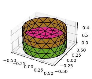
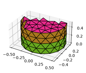
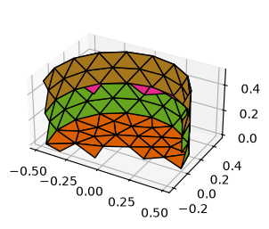
并行版本. 每个进程只持有网格的一部分, view() 输出的
Number of 0-cells per rank: ... 会按进程逐个列出本进程可见的实体个数.
The parallel version. Every process only holds part of the mesh, and the
Number of 0-cells per rank: ... in the output of view() lists process by
process the number of entities visible to it.
%%px --block
import matplotlib.pyplot as plt
import numpy as np
from py.intro_utils import triplot

cylinder = Mesh("gmsh/cylinder.msh")
fig, axes = plt.subplots(figsize=[4, 3], subplot_kw={'projection': '3d'})
triplot(cylinder, axes=axes)
axes.set_aspect('equal')
cylinder.topology_dm.view()
[stdout:0] DM Object: firedrake_default_topology 2 MPI processes
  type: plex
firedrake_default_topology in 3 dimensions:
  Number of 0-cells per rank: 104 109
  Number of 1-cells per rank: 468 476
  Number of 2-cells per rank: 637 640
  Number of 3-cells per rank: 272 272
Labels:
  depth: 4 strata with value/size (0 (104), 1 (468), 2 (637), 3 (272))
  celltype: 4 strata with value/size (0 (104), 1 (468), 3 (637), 6 (272))
  Cell Sets: 2 strata with value/size (1 (136), 2 (136))
  Face Sets: 5 strata with value/size (3 (125), 4 (129), 5 (129), 6 (129), 7 (129))
  Edge Sets: 1 strata with value/size (1 (9))
  exterior_facets: 1 strata with value/size (1 (459))
  interior_facets: 1 strata with value/size (1 (1047))
  pyop2_core: 1 strata with value/size (1 (742))
  pyop2_owned: 1 strata with value/size (1 (470))
  pyop2_ghost: 1 strata with value/size (1 (269))
[output:1]
[output:0]
三维的做法和二维同构, 只是各维度升一级. 对接触线上属于本进程的每一段 (Edge Sets
里 tag 为 1 的那些边), 在它的 support (所有含这条边的面) 里找那个既属于界面
(Face Sets 的 tag 3)、又是本进程 core 或 owned 的三角形; 这个三角形的三个顶点就是该段的两个端点, 加上用 np.setdiff1d 从面的闭包里挑出来的第三个顶点. 最后同样用
global_numbering 把点号换成节点号, 得到一张形状为 (三角形数, 3) 的 cell_node_map.
中间那句 assert ... getDof(_) > 0 是在确认这些顶点上确实有 CG1 的自由度.
并行时这段代码有个隐患: 本进程的 contact_line 里可能混进影子段, 它们找不到
core 或 owned 的界面三角形, 于是 faces 会比 contact_line 短, 而下一步的
zip(contact_line, faces) 会静默截断, 不报任何错. 实测 2 进程下就有一个进程是
9 段对 8 个面, 目前没出乱子只是因为那个没配上的影子段恰好排在最后一位. 稳妥的写法是在同一个循环里把 (段, 面) 成对收集, 而不是先分别建两个列表再 zip.
The three-dimensional procedure is isomorphic to the two-dimensional one, with
every dimension raised by one. For every segment of the contact line that belongs
to this process (the edges with tag 1 in Edge Sets), among its support (all the
faces containing that edge) one looks for the triangle that belongs to the
interface (tag 3 of Face Sets) and is core or owned on this process; the three
vertices of that triangle are the two end points of the segment, plus the third
vertex picked out of the closure of the face with np.setdiff1d. Finally the
point numbers are again turned into node numbers with global_numbering, giving
a cell_node_map of shape (number of triangles, 3). The
assert ... getDof(_) > 0 in the middle checks that these vertices really carry
CG1 degrees of freedom.
This code has one pitfall in parallel: the contact_line of a process may
contain ghost segments, which find no core or owned interface
triangle, so that faces ends up shorter than contact_line, and the
zip(contact_line, faces) of the next step truncates silently, without
raising anything. In practice, on 2 processes one of them has 9 segments against
8 faces; nothing has gone wrong so far only because the segment that found no
match happens to be the last one. The safe way to write this is to collect the
(segment, face) pairs together in one loop, instead of building two lists
separately and then calling zip.
def get_interface_element_include_contact_line(mesh, V, interface_tag, contact_line_tag):
    dm = mesh.topology_dm

    edge_label = dm.getLabel("Edge Sets")
    face_label = dm.getLabel("Face Sets")
    core_label = dm.getLabel("pyop2_core")
    owned_label = dm.getLabel("pyop2_owned")

    edge_label_values = edge_label.getValueIS().indices
    contact_line = []
    if contact_line_tag in edge_label_values:
        contact_line = edge_label.getStratumIS(contact_line_tag).indices

    faces = []
    for seg in contact_line:
        for face in dm.getSupport(seg):
            if face_label.getValue(face) == interface_tag and \
                (core_label.getValue(face) == 1 or owned_label.getValue(face) == 1):
                faces.append(int(face))
                break

    plex_cell_node_map = np.zeros((len(faces), 3), dtype=np.int32)
    for i, (seg, face) in enumerate(zip(contact_line, faces)):
        seg_nodes = dm.getCone(seg)
        plex_cell_node_map[i, :2] = seg_nodes
        plex_cell_node_map[i, 2:] = np.setdiff1d(
            np.unique(np.array([dm.getCone(_) for _ in dm.getCone(face)]).flatten()),
            seg_nodes)

    local_section = V.global_numbering  # global_numbering is a local section
    cell_node_map = np.zeros_like(plex_cell_node_map)
    for i, cell in enumerate(plex_cell_node_map):
        assert np.all(np.array([local_section.getDof(_) for _ in cell]) > 0)
        cell_node_map[i, :] = [local_section.getOffset(_) for _ in cell]

    return cell_node_map

CONTACT_LINE = 1
INTERFACE = 3
V = FunctionSpace(cylinder, 'CG', 1)
cell_node_map = get_interface_element_include_contact_line(cylinder, V, INTERFACE, CONTACT_LINE)
并行版本. 这张网格的接触线一共 16 段, 这一次的分区下由两个进程分别持有其中一部分;
注意每个进程的 contact_line 里还可能带上邻居的影子段, 因此两边的段数之和会比 16 大
(实测是 8 和 9). 两个进程的 cell_node_map 合起来才是完整的一圈.
The parallel version. The contact line of this mesh has 16 segments in total,
which under the partitioning obtained this time are held partly by each of the two processes; note that the contact_line of a process may also carry ghost
segments of its neighbor, so that the numbers of segments of the two sides add up
to more than 16 (8 and 9 in practice). Only the cell_node_map of the two
processes taken together form the complete ring.
%%px --block
def get_interface_element_include_contact_line(mesh, V, interface_tag, contact_line_tag):
    dm = mesh.topology_dm

    edge_label = dm.getLabel("Edge Sets")
    face_label = dm.getLabel("Face Sets")
    core_label = dm.getLabel("pyop2_core")
    owned_label = dm.getLabel("pyop2_owned")

    edge_label_values = edge_label.getValueIS().indices
    contact_line = []
    if contact_line_tag in edge_label_values:
        contact_line = edge_label.getStratumIS(contact_line_tag).indices

    faces = []
    for seg in contact_line:
        for face in dm.getSupport(seg):
            if face_label.getValue(face) == interface_tag and \
                (core_label.getValue(face) == 1 or owned_label.getValue(face) == 1):
                faces.append(int(face))
                break

    plex_cell_node_map = np.zeros((len(faces), 3), dtype=np.int32)
    for i, (seg, face) in enumerate(zip(contact_line, faces)):
        seg_nodes = dm.getCone(seg)
        plex_cell_node_map[i, :2] = seg_nodes  # set the seg nodes first
        plex_cell_node_map[i, 2:] = np.setdiff1d(
            np.unique(np.array([dm.getCone(_) for _ in dm.getCone(face)]).flatten()),
            seg_nodes)

    local_section = V.global_numbering  # global_numbering is a local section
    cell_node_map = np.zeros_like(plex_cell_node_map)
    for i, cell in enumerate(plex_cell_node_map):
        assert np.all(np.array([local_section.getDof(_) for _ in cell]) > 0)
        cell_node_map[i, :] = [local_section.getOffset(_) for _ in cell]

    return cell_node_map

CONTACT_LINE = 1
INTERFACE = 3
V = FunctionSpace(cylinder, 'CG', 1)
cell_node_map = get_interface_element_include_contact_line(cylinder, V, INTERFACE, CONTACT_LINE)
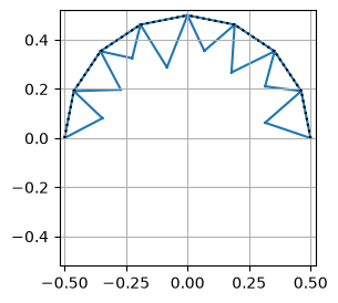
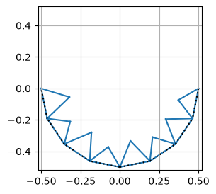
把找到的三角形画出来验证: 先断言它们的顶点 z 坐标都等于 0.25, 也就是确实落在界面上; 再在 xy 平面里画出这些三角形, 用黑色虚线标出其中落在接触线上的那条边. 看到的应是沿着圆周排开的一圈三角形.
Plot the triangles that were found, to check them: first assert that the z coordinates of their vertices are all equal to 0.25, so that they do lie on the interface; then draw these triangles in the xy plane, marking with a black dashed line the edge of each triangle that lies on the contact line. What one should see is a ring of triangles arranged along the circumference.
# plot the triangle to check if they are on the interface
coords = cylinder.coordinates.dat.data_ro_with_halos
if len(cell_node_map) > 0:
    assert np.allclose(coords[:, 2][cell_node_map], 0.25)
    fig, axes = plt.subplots(figsize=[4, 3])
    c = axes.triplot(coords[:, 0], coords[:, 1], triangles=cell_node_map)
    lines = [[(coords[_, 0], coords[_, 1]) for _ in __[:2] ] for __ in cell_node_map]
    from matplotlib.collections import LineCollection
    line_collection = LineCollection(lines, colors='k', linestyles=':')
    axes.add_collection(line_collection)
    axes.set_xlim([-0.52, 0.52])
    axes.set_ylim([-0.52, 0.52])
    axes.set_aspect("equal")
    axes.grid("on")
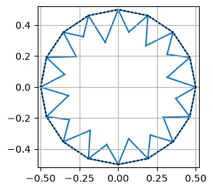
并行版本, 每个进程画自己持有的那一部分.
The parallel version; every process draws the part it holds.
%%px --block
# plot the triangle to check if they are on the interface
coords = cylinder.coordinates.dat.data_ro_with_halos
if len(cell_node_map) > 0:
    assert np.allclose(coords[:, 2][cell_node_map], 0.25)
    fig, axes = plt.subplots(figsize=[4, 3])
    c = axes.triplot(coords[:, 0], coords[:, 1], triangles=cell_node_map)
    lines = [[(coords[_, 0], coords[_, 1]) for _ in __[:2] ] for __ in cell_node_map]
    from matplotlib.collections import LineCollection
    line_collection = LineCollection(lines, colors='k', linestyles=':')
    axes.add_collection(line_collection)
    axes.set_xlim([-0.52, 0.52])
    axes.set_ylim([-0.52, 0.52])
    axes.set_aspect("equal")
    axes.grid("on")
[output:1]
[output:0]